Single line fire alarm line fixing clamp

A technology for fixing clamps and police lines, applied in electrical components and other directions, it can solve the problems of product failure, low material strength, unusability, etc., and achieve the effect of strong deformation resistance, good corrosion resistance and space saving.

Pending Publication Date: 2018-01-05
DALIAN CANDL TECH DEV CO LTD
5 Cites 1 Cited by

AI-Extracted Technical Summary

Problems solved by technology

[0003] Traditional clamps can only be used in general areas, and the material strength is low, and the bending part of the clamp is easy to break, which cannot meet the aviation and aerospace standards; the structure of the traditional...

Method used

Further, an included angle is provided between the front end part of the upper pressing sheet 2 and the base 1 when they are fastened together with the front end part of the base 1, and this included angle is greater than or equal to 5 ° and less...

Abstract

The invention discloses a single line fire alarm line fixing clamp which comprises a base, an upper pressing piece, a compression screw and a compression screw pin. The tail end of the base is hingedto the tail end of the upper pressing piece through a rotating shaft; after the upper pressing piece and the base are relatively overturned and buckled, an arc-shaped part of the base and an arc-shaped part of the upper pressing piece are buckled to form a hole; a cross hole is formed in the front end of the base; with respect to two strip holes perpendicular to each other in the cross hole, the width of one strip hole is larger than that of the other strip hole; a round hole is formed in the position of the upper pressing piece above the cross hole, and it is ensured that a rod body part of the compression screw can penetrate a center hole of the cross hole. According to the technical scheme, due to the fact that the length of the compression screw pin is greater than the diameter of theround hole of the upper pressing piece, the compression screw does not drop from the upper pressing piece, the upper pressing piece and the base are buckled, the compression screw is correspondingly rotated to make the compression screw pin correspond to the strip hole, with a larger width, of the cross hole of the base, the upper pressing piece continues to be pressed to make the compression screw pin penetrate the bottom of the cross hole, and rotation through 90 degrees is performed to complete locking.

Application Domain

Electrical apparatus

Technology Topic

Structural engineeringMechanical engineering +2

Image

  • Single line fire alarm line fixing clamp
  • Single line fire alarm line fixing clamp
  • Single line fire alarm line fixing clamp

Examples

  • Experimental program(1)

Example Embodiment

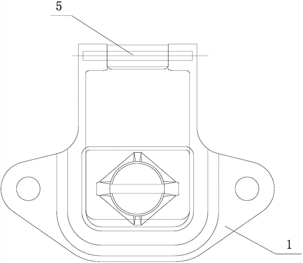
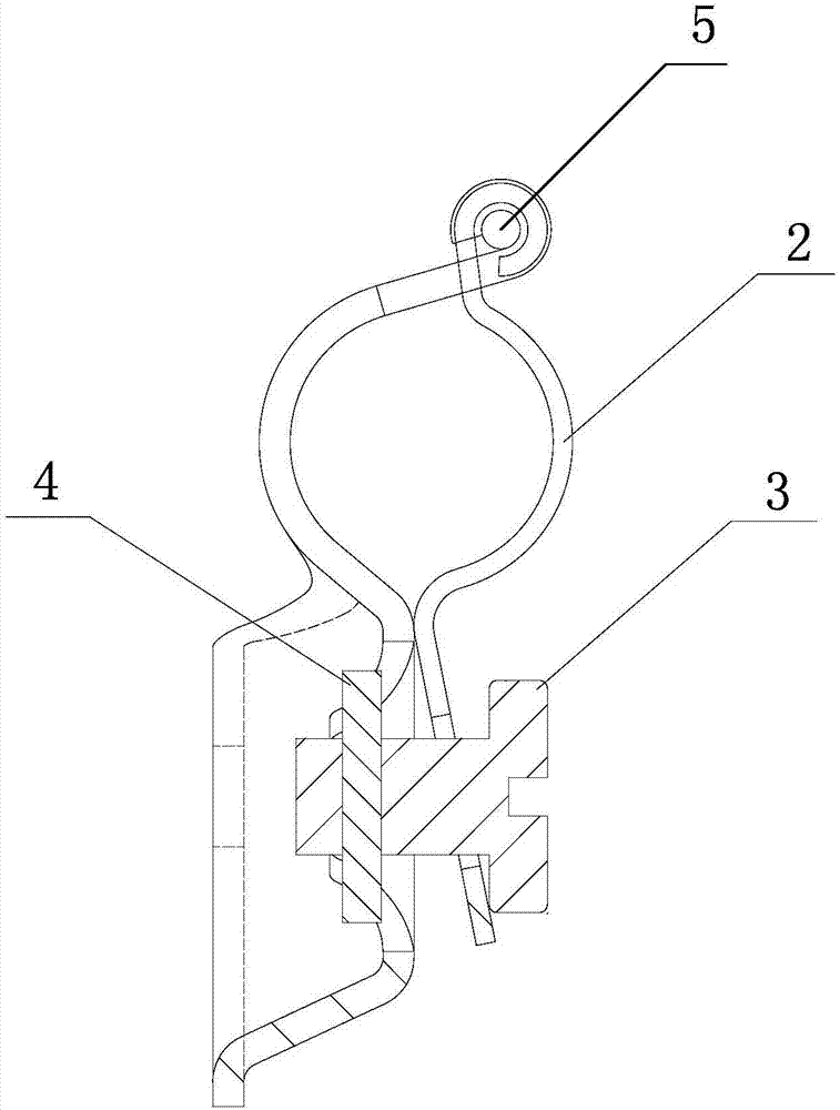
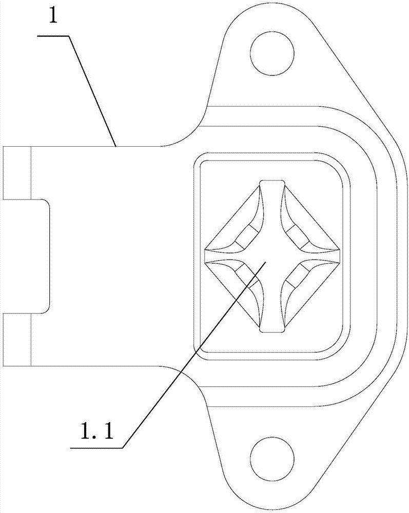
[0030] Such as figure 1 , figure 2 , image 3 with Figure 4 A single-wire fire alarm wire fixing clamp shown includes: a base 1, an upper pressing piece 2, a compression screw 3, and a compression screw pin 4;
[0031] The tail end of the base 1 and the tail end of the upper pressing plate 2 are hinged through the shaft 5;
[0032] Among them, the hinged part of the base 1 close to the shaft 5 is provided with a downwardly concave arc-shaped part, the upper pressing piece 2 is provided with an upwardly convex arc-shaped part above the corresponding position of the arc-shaped part of the base 1, and the upper pressing piece 2 is flipped and buckled with the base 1. The arc-shaped part of the back base 1 is buckled with the arc-shaped part of the upper pressing piece 2 to form a hole; the left and right sides of the base 1 are each provided with a base mounting hole;
[0033] The front end of the base 1 is processed with a cross hole 1.1;
[0034] Among them, the cross hole 1.1 is two vertical holes, one of which has a larger aperture width than the other;
[0035] After the upper pressing piece 2 is fastened with the base 1, a round hole for the compression screw 3 to pass through is processed at the front end part above the cross hole 1.1;
[0036] The compression screw pin 4 is vertically fixed to the end of the compression screw 3, and the length of the compression screw pin 4 is greater than the diameter of the round hole of the upper pressing piece 2;
[0037] Among them, the diameter of the rod part of the compression screw 3 is less than or equal to the diameter of the center hole of the cross hole 1.1 of the base 1 to ensure that the rod part of the compression screw 3 can pass through the center hole of the cross hole 1.1; the width of the compression screw pin 4 is greater than that of the cross hole 1.1 The width of the hole 1.1 is smaller and the hole diameter is smaller than or equal to the width of the cross hole 1.1.
[0038] In the present invention adopting the above technical solution, the rod body of the compression screw 3 passes through the circular hole of the upper compression plate 2, and then the compression screw pin 4 is assembled. Since the length of the compression screw pin 4 is greater than the diameter of the circular hole of the upper compression plate 2, In this way, the pressing screw 3 will not fall off from the upper pressing piece 2, and then buckle the upper pressing piece 2 and the base 1, and correspondingly rotate the pressing screw 3 to make the screw pin 4 and the cross hole 1.1 of the base 1 wider. If the hole corresponds, continue to press the upper pressing piece 2 to make the tightening screw pin 4 pass through the bottom end of the cross hole 1.1, and then rotate 90° to complete the locking work, and then rotate 90° correspondingly to open.
[0039] Further, the cross hole 1.1 is a punched cross hole, that is, there are 4 downwardly bent and folded flanges 1.11 at the lower end of the cross hole; the function of this structure is to compress the screw pin 4 when the compression screw 3 is rotated by 90° and locked. It will be embedded in the gap formed by the protruding edge portion 1.11 at the bottom end of the narrow strip hole. First, a limit of the compression screw pin 4 is realized, which can prevent the compression screw pin 4 from moving in series.
[0040] Further, an included angle is set between the front end portion of the upper pressing piece 2 and the base 1 after the base 1 is buckled, and the included angle is greater than 5° and less than 60°. The function of this structure is to provide the upper pressing piece 2 with The base 1 is buckled to provide a pre-tightening force, and in combination with the above solution, a larger pre-tightening force is provided, which further prevents the compression screw pin 4 from moving in tandem.
[0041] Further, the connection mode of the compression screw pin 4 and the compression screw 3 is threaded connection or riveting;
[0042] Further, the base 1, the upper pressing piece 2, the pressing screw 3, the pressing screw pin 4, and the rotating shaft 5 are all made of stainless steel.
[0043] The above are only the preferred embodiments of the present invention, and are not intended to limit the present invention in any form. Although the present invention has been disclosed as above in preferred embodiments, it is not intended to limit the present invention. Anyone familiar with the profession Without departing from the scope of the technical solution of the present invention, the skilled person can use the technical content disclosed above to make some changes or modification into equivalent embodiments with equivalent changes, but any content that does not deviate from the technical solution of the present invention, according to the present invention Any simple modifications, equivalent changes and modifications made to the above embodiments are still within the scope of the technical solutions of the present invention.

PUM

no PUM

Description & Claims & Application Information

We can also present the details of the Description, Claims and Application information to help users get a comprehensive understanding of the technical details of the patent, such as background art, summary of invention, brief description of drawings, description of embodiments, and other original content. On the other hand, users can also determine the specific scope of protection of the technology through the list of claims; as well as understand the changes in the life cycle of the technology with the presentation of the patent timeline. Login to view more.

Similar technology patents

Austenitic stainless steel forging and production process thereof

ActiveCN103147018AGood corrosion resistanceExcellent cold workability
Owner:WUXI PAIKE HEAVY CASTING & FORGING

Classification and recommendation of technical efficacy words

  • stable structure
  • Good corrosion resistance

Silicon/carbon composite microsphere negative electrode material as well as preparation method and application for same

ActiveCN103311522Astable structureImprove charge and discharge cycle life
Owner:INST OF PROCESS ENG CHINESE ACAD OF SCI

Preparation method of magnetic graphene based oil absorption foam material

Owner:XINJIANG TECHN INST OF PHYSICS & CHEM CHINESE ACAD OF SCI

MIM manufacturing process for non-magnetic 17-4P stainless steel parts

InactiveCN105537595AGood corrosion resistanceHigh tensile strength and yield
Owner:SHANGHAI FUTURE HIGH-TECH CO LTD

High isolation protection material and preparation method thereof

Owner:THE QUARTERMASTER EQUIPMENT RESEARCH INSTITUTE OF THE GENERAL LOGISITIC DEPARTME +1
Why Eureka
Try Eureka