High-efficiency chemical production homogenization device

A technology for chemical production and homogenization device, applied in clay preparation device, cement mixing device, mixer with rotating mixing device, etc., can solve the problems of low production efficiency, heavy load, long time, etc. The effect of homogenized quality

Inactive Publication Date: 2018-01-09
新乡市巨能合成材料有限公司
View PDF4 Cites 4 Cited by
  • Summary
  • Abstract
  • Description
  • Claims
  • Application Information

AI Technical Summary

Problems solved by technology

[0002] By adopting certain technological measures, it is possible to reduce the fluctuation amplitude of the chemical composition of the material and make the chemical composition of the material uniform. Especially in the field of large-scale commercial concrete production and preparation, it is necessary to add cement, fly ash, mineral powder, and powder Concrete raw materials such as admixtures are uniformly mixed by stirring, while in the current traditional technology, various concrete powder raw materials are directly weighed and measured, and then directly put into the concrete mixing main machine, and the homogenization and mixing are completely relied on the concrete mixing main machine function, due to the large power and heavy load of the mixing host, it will consume a large amount of electric energy and a long time to complete this function, which will inevitably lead to low production efficiency and relatively increase the cost of commercial concrete manufacturing. Various powdery raw materials are directly Putting it into the mixing machine, especially powdery trace additives, cannot be fully mixed evenly, which will affect the quality of commercial concrete, so that the existing technology and equipment cannot effectively meet the production needs

Method used


Image

  • High-efficiency chemical production homogenization device
  • High-efficiency chemical production homogenization device

Examples


Embodiment Construction

[0014] The following will clearly and completely describe the technical solutions in the embodiments of the present invention with reference to the accompanying drawings in the embodiments of the present invention. Obviously, the described embodiments are only some, not all, embodiments of the present invention.

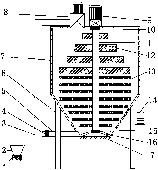
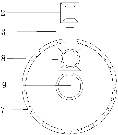
[0015] refer to Figure 1-2 , a high-efficiency chemical production homogenization device, comprising a homogenization tank 7, the bottom of the homogenization tank 7 is an open structure, and the outer wall of the bottom end of the homogenization tank 7 is fixed with a door 17 by a hinge, the homogenization tank 7 The inner wall of the bottom end is welded with a rotating shaft bracket 16, and the rotating shaft bracket 16 is an X-shaped structure. The center position of the rotating shaft bracket 16 is welded with a bearing seat, and the inner wall of the bearing seat is sleeved with a second bearing 15. The top of the homogenizing tank 7 There is an opening at the...


PUM


Abstract

The invention discloses a high-efficiency chemical production homogenization device which comprises a homogenization tank, wherein the bottom end of the homogenization tank is in an open structure; abin gate is fixed on an outer wall of the bottom end of the homogenization tank by hinges; a rotating shaft bracket is welded on an inner wall of the bottom end of the homogenization tank, and is in an X-shaped structure; a bearing pedestal is welded in the center of the rotating shaft bracket; a second bearing is connected on an inner wall of the bearing pedestal in a sleeving manner; an openingis formed in a center point of the top end of the homogenization tank; a first bearing is connected on an inner wall of the opening in a sleeving manner; and a rotating shaft is connected between thefirst bearing and the second bearing in a sleeving manner. According to the homogenization device, the homogenization tank is additionally arranged, and two stirring blades in different sizes are additionally arranged in the homogenization tank, so that a raw material can be homogenized in layers; and a circulating pipe is additionally arranged at the bottom end, so that the precipitated and unhomogenized raw material can be conveyed to the top of the homogenization tank by a conveying pipe for homogenization again, and the homogenization efficiency and the homogenization quality can be improved.

Description

technical field [0001] The invention relates to the technical field of chemical production, in particular to a high-efficiency chemical production homogenization device. Background technique [0002] By adopting certain technological measures, it is possible to reduce the fluctuation amplitude of the chemical composition of the material and make the chemical composition of the material uniform. Especially in the field of large-scale commercial concrete production and preparation, it is necessary to add cement, fly ash, mineral powder, and powder Concrete raw materials such as admixtures are uniformly mixed by stirring, while in the current traditional technology, various concrete powder raw materials are directly weighed and measured, and then directly put into the concrete mixing main machine, and the homogenization and mixing are completely relied on the concrete mixing main machine function, due to the large power and heavy load of the mixing host, it will consume a large...

Claims


Application Information

Patent Timeline
IPC IPC(8): B01F7/20B01F5/10B28C5/38B01F27/906
Inventor 周忠太张小涛张齐亮孟红文
Owner 新乡市巨能合成材料有限公司
Why Eureka
Try Eureka