Resin molding apparatus and method for manufacturing resin molded product

A technology of resin molding and manufacturing methods, applied in semiconductor/solid-state device manufacturing, electrical components, circuits, etc., can solve problems such as positional deviation of resin molded products, and achieve the effect of reducing molding defects

Active Publication Date: 2018-01-09
TOWA
View PDF3 Cites 0 Cited by
  • Summary
  • Abstract
  • Description
  • Claims
  • Application Information

AI Technical Summary

Problems solved by technology

When the guide pins 28 are deformed due to wear or damage, the substrate may not be normally positioned to the prescribed position of the upper mold 10a
Furthermore, if the resin molding is performed without checking whether it is properly positioned after the positioning operation, the resin molded product may have positional deviation defects without proper positioning.

Method used


Image

  • Resin molding apparatus and method for manufacturing resin molded product
  • Resin molding apparatus and method for manufacturing resin molded product
  • Resin molding apparatus and method for manufacturing resin molded product

Examples


Embodiment approach 1

[0086] (Structure of resin molding device)

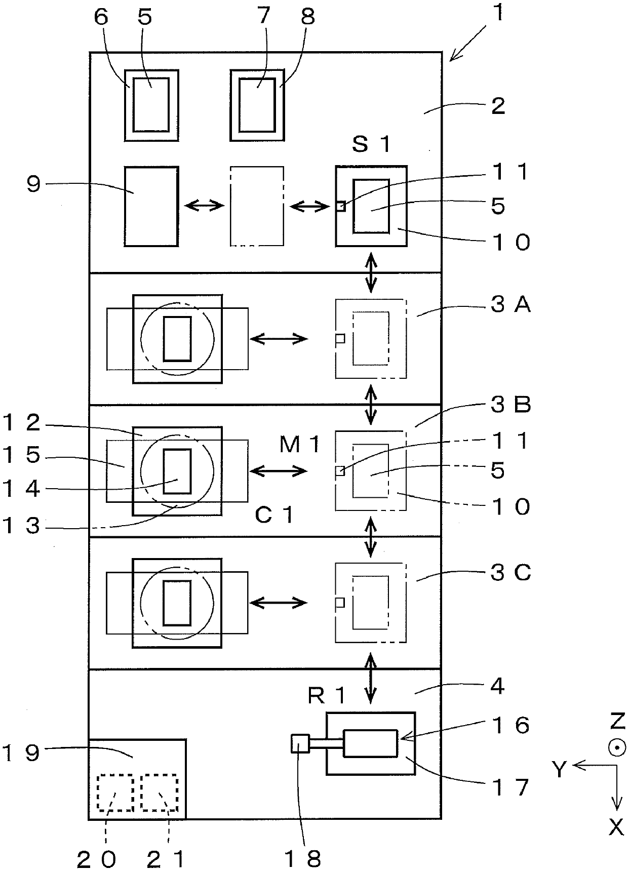
[0087] refer to figure 1 , the configuration of the resin molding apparatus according to Embodiment 1 of the present invention will be described. figure 1 The shown resin molding apparatus 1 is, for example, a resin molding apparatus using a compression molding method. An example of using a fluid resin, that is, a liquid resin, as the resin material is shown.

[0088] The resin molding apparatus 1 includes a substrate supply and storage module 2, three molding modules 3A, 3B, and 3C, and a resin supply module 4 as constituent elements. The substrate supply and storage module 2, the molding modules 3A, 3B, and 3C, and the resin supply module 4, which are structural elements, are mutually detachable and replaceable with respect to other structural elements.

[0089] The substrate supply and storage module 2 is provided with: a pre-encapsulation substrate supply part 6, which supplies the pre-encapsulation substrate 5; a post-enca...

Embodiment approach 2

[0175] refer to Figure 8 ~ Figure 9 , the operation of verifying whether or not the pre-package substrate 5 supplied to the upper mold 23 is normally positioned in Embodiment 2 will be described. The difference from Embodiment 1 is that the positioning is verified by photographing two positions at the ends of the pre-packaging substrate 5 along the X direction and the Y direction. Accordingly, not only the X direction and the Y direction but also the θ direction can be verified to verify whether the positioning is performed normally. The other operations (manufacturing method) and the configuration of the molding die are the same as those in Embodiment 1, and thus description thereof will be omitted.

[0176] (Position verification operation of substrate (part of manufacturing method of resin molded product))

[0177] Next, the operation of verifying whether or not the pre-packaging substrate 5 is normally positioned in Embodiment 2 will be described. The description here ...

Embodiment approach 3

[0202] refer to Figure 10 , the operation of verifying whether or not the pre-package substrate 5 supplied to the upper mold 23 is normally positioned in Embodiment 3 will be described. The description here is also a description of a part of the manufacturing method of the resin molded article. The difference from Embodiment 1 is that the upper mold 23 is provided with a U-shaped reference mark including the X direction and the Y direction, and the position of the corner of the substrate is used for data processing. The configuration and operation (manufacturing method) of the other molding dies are the same as those in Embodiment 1, and thus description thereof will be omitted.

[0203] Next, the operation of verifying whether or not the pre-packaging substrate 5 is normally positioned in Embodiment 3 will be described. Such as Figure 10 As shown in (a), a U-shaped reference mark 36 is provided on the mold surface of the upper mold 23 . In this embodiment, for example, ...


PUM


Abstract

The invention relates to a resin molding apparatus and a method of manufacturing a resin molded product that verify whether a substrate supplied to a molding die is properly positioned or not. The apparatus includes a molding die 24 having a first die 23 and a second die 12 opposed to each other, a substrate feeding mechanism 10 for feeding a substrate to a die surface of the first die 23, a positioning mechanism that positions a positioning object 5 that includes at least a substrate; a mold clamping mechanism that molds the molding die 24; a camera 11 that is disposed between the first die and the second die when the molding die 24 is opened; and a processor that performs processing on image data captured by the camera. The first die has reference marks 29,30 which can be identified through photographing of the camera 11, and the camera 11 takes an image of the positioned object 5 and the reference marks 29 and 30. The processor 11 determines whether the object 5 is normally positioned according to the image data of the object 5 and the reference marks 29,30 captured by camera 11.

Description

technical field [0001] The present invention relates to a resin molding device used when resin-encapsulating chip-shaped electronic components (hereinafter appropriately referred to as "chips") such as transistors, integrated circuits (IC, Integrated Circuit), and light emitting diodes (LED, Light Emitting Diode). and a method for producing a resin molded product. Background technique [0002] Conventionally, a resin molding device is used to resin-encapsulate a semiconductor chip or the like mounted on a substrate. In the resin molding apparatus, the semiconductor chip is resin-encapsulated by positioning the substrate at a predetermined position of the molding die and clamping the molding die. As a technique for positioning the substrate at a predetermined position on the molding die, for example, there is a technique of bringing the outer surface of the substrate into contact with guide pins provided on the molding die (see Patent Document 1). [0003] Patent Document 1...

Claims


Application Information

Patent Timeline
Patent Type & Authority Applications(China)
IPC IPC(8): B29C43/18B29C43/36H01L21/56
CPCB29C43/18B29C43/58B29C2043/181B29C2043/3602B29C2043/5833B29C2043/5891H01L21/565
Inventor 后藤智行岩田康弘花坂周邦
Owner TOWA
Why Eureka
Try Eureka