Trolley limiting buffer device of bridge crane

An overhead crane and buffer device technology, applied in the field of trolley spare parts, can solve the problems of increased cost, unstable goods, loss of vehicle gear and buffer, and achieve the effects of speeding up the limit speed, saving man-hours and having a simple structure

Inactive Publication Date: 2018-01-09
SHAOGUAN TAILI CRANE
View PDF6 Cites 8 Cited by
  • Summary
  • Abstract
  • Description
  • Claims
  • Application Information

AI Technical Summary

Problems solved by technology

[0004] (1) The limit device of the existing bridge crane first realizes the deceleration and power-off process of the trolley by touching the two proximity switches on the trolley track with the safety ruler on the trolley, but this process requires complicated design and installation. circuits and components, which increase the cost;
[0005] (2) The limit device of the existing simple bridge crane generally relies on installing the buffers on the left and right sides of the trolley to collide with the gears at both ends of the trolley track to stop the trolley. Although this method does little damage to the trolley, if it is The car running at high speed is forcibly limited by the car gear, which will cause huge loss to the car gear and buffer;
[0006] (3) When the existing limit device of the bridge crane collides with the buffer of the trolley, if the speed of the trolley is very high before the collision, the trolley will rebound for a certain distance due to the collision between the buffer and the gear, so that the hoisted car directly below The goods are unstable due to shaking, which prolongs the loading and unloading time of the goods and wastes man-hours

Method used


Image

  • Trolley limiting buffer device of bridge crane
  • Trolley limiting buffer device of bridge crane

Examples


Embodiment

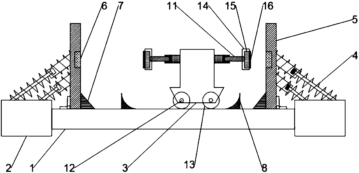
[0025] Such as figure 1 As shown, the present invention provides a trolley limit buffer device for a bridge crane, including a trolley track 1, which allows the trolley to translate left and right on the beam, and the two ends of the trolley track 1 are fixedly installed with end beams 2, and the end beams The beam 2 is perpendicular to the trolley track 1, the trolley track 1 is provided with a trolley frame 3, the left and right sides of the trolley frame 3 are fixed with hydraulic rods 11, and the top surface of the end beam 2 passes through the shock absorber 4 Connected with a gear 5, the shock absorber 4 is installed obliquely and is a rod-shaped shock absorber 4, the number of the shock absorber 4 can be selected according to the size of the collision force, and the shock absorber 4 adopts a hydraulic shock absorber or Spring shock absorbers and hydraulic shock absorbers have a better cushioning effect than spring shock absorbers, but the cost of spring shock absorbers ...


PUM


Abstract

The invention discloses a trolley limiting buffer device of a bridge crane. The trolley limiting buffer device comprises a trolley rail, and end beams are fixedly mounted at the two ends of the trolley rail; a trolley frame is arranged on the trolley rail; the top surfaces of the end beams are connected with car stops through shock absorbers; magnets are mounted at the centers of the side surfacesof the car stops through mounting holes; the car stops are hinged to the top surface of the trolley rail; wheel chocks are further mounted in the positions, between the two car stops, on the trolleyrail; hydraulic rods are fixedly mounted on the left and right sides of the trolley frame; wheels are mounted on the trolley frame through wheel shafts; and cylindrical magnets are mounted at one endsof the hydraulic rods through mounting sleeves. According to the trolley limiting buffer device, the hydraulic rods are in contact with the car stops hinged to the trolley rail, buffer and limiting are achieved, during collision, the wheels are buffered and decelerated through rotation of the car stops and deceleration strips in the wheel chocks, collision force is smaller, the car stops and thehydraulic rods are protected, rebound force of a trolley is smaller, double buffer and limiting for the trolley are achieved, the structure is simple, cost is low, and loading and unloading efficiencyof the crane is high.

Description

technical field [0001] The invention relates to the technical field of trolley spare parts for bridge cranes, in particular to a trolley limit buffer device for bridge cranes. Background technique [0002] As an important lifting equipment in large-scale industrial production, metallurgy, and mechanical equipment, cranes have high requirements for safety and reliability, and there is no exception. For the sake of safety, a safety switch is installed on the cart of the bridge crane, and a safety limit switch and an electromagnetic brake system are installed on the trolley and the main hook. These methods effectively protect the safe operation of the crane. The limit switch of the bridge crane includes limit switches such as beams, trolleys, and main hooks. Among them, the direct-acting travel switch uses the moving object to hit the movable part to make the contact on or off, thereby To complete the unblocking of the circuit. During the working process, the crane is not alw...

Claims


Application Information

Patent Timeline
Patent Type & Authority Applications(China)
IPC IPC(8): B66C7/16B66C15/00
Inventor 焦来文
Owner SHAOGUAN TAILI CRANE
Why Eureka
Try Eureka