A drilling transverse beam moving mechanism of a drilling machine

A technology of moving mechanism and transverse beam, which is applied in drilling/drilling equipment, boring/drilling, metal processing machinery parts, etc., can solve the problems of affecting the travel, increasing the weight of the transverse beam, and large screw diameter, etc. Achieve the effect of reducing weight, reducing energy consumption, and light weight

Active Publication Date: 2021-08-03
济宁拓源精密机械股份有限公司
View PDF0 Cites 0 Cited by
  • Summary
  • Abstract
  • Description
  • Claims
  • Application Information

AI Technical Summary

Problems solved by technology

[0002] The main machine head at the drill bit or milling cutter of the existing drilling machine or engraving machine generally moves left and right along the transverse beam to realize position adjustment, while the existing transverse beam is generally equipped with a single screw for rotational drive, and The single screw needs to ensure that its strength meets the load-bearing requirements of the main machine head, and the diameter of the screw needs to be large, so that the power of the driving motor needs to be large enough, which increases the weight of the entire transverse beam;
[0003] At the same time, the limit of the moving position of the existing main engine head is determined by the rotation speed of the rotating shaft of the driving motor. The driving motor needs to use a servo motor, and when the number of rotations is controlled by an input error, the stroke will be affected. walk around

Method used


Image

  • A drilling transverse beam moving mechanism of a drilling machine
  • A drilling transverse beam moving mechanism of a drilling machine
  • A drilling transverse beam moving mechanism of a drilling machine

Examples


Embodiment

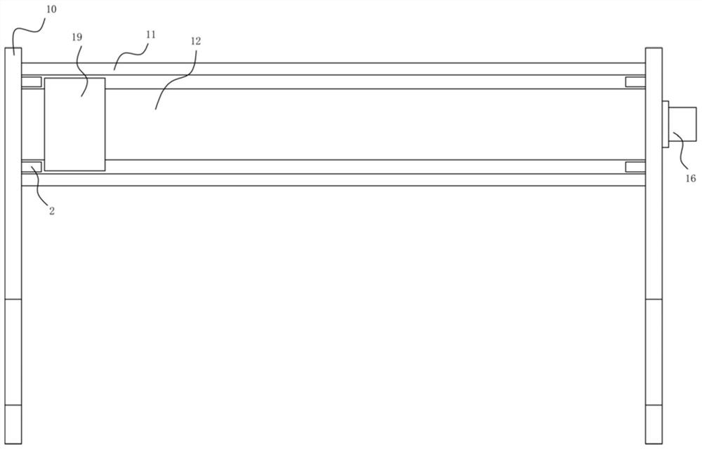
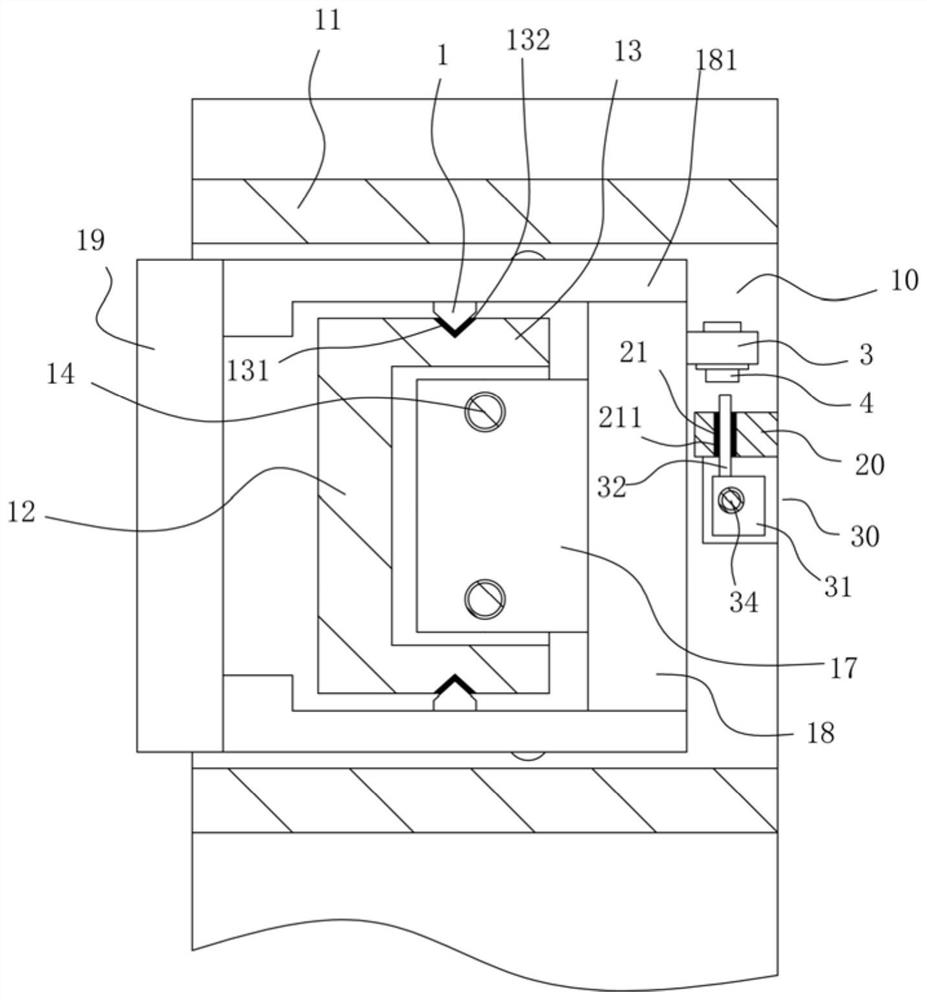
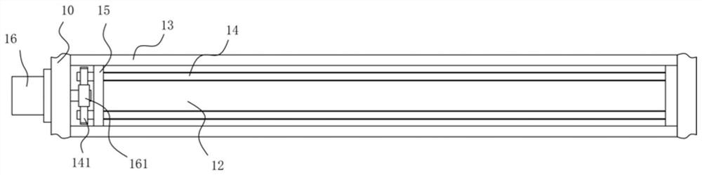
[0021] Example: see Figure 1 to Figure 4 As shown, a drilling transverse beam moving mechanism of a drilling machine includes two side support plates 10, and the upper part between the two side support plates 10 is welded and fixed with two transverse beam plates 11 arranged up and down. A transverse guide plate 12 is arranged between the two transverse beam plates 11, the upper and lower parts of the rear wall of the transverse guide plate 12 are formed with horizontal extensions 13, and the two ends of the transverse guide plate 12 and the horizontal extension 13 are all welded and fixed on the two sides. On each side support plate 10, two transmission screw rods 14 are arranged between the two horizontal extensions 13, and an end connection plate 15 is arranged between the left and right ends of the two horizontal extensions 13, and the two ends of the end connection plate 15 The ends are welded and fixed on the two horizontal extensions 13, the two ends of the transmissio...


PUM


Abstract

The invention discloses a drilling transverse beam moving mechanism of a drilling machine, which comprises two side support plates, and the upper part between the two side support plates is welded and fixed with two transverse beam plates arranged up and down. There is a transverse guide plate between the beams and plates, and the upper and lower parts of the rear wall of the transverse guide plate are formed with horizontal extensions, which are driven by two small-diameter transmission screws while ensuring the same strength as the original single screw. , the two small-diameter transmission screws used are light in weight, thereby reducing the weight of the entire transverse beam mechanism, and at the same time, the low-power main drive servo motor is used to reduce manufacturing costs and energy consumption, and it is passed through the rotation of the main drive servo motor While controlling the moving position of the main moving block driven by the number, by adjusting the position of the two vertical sensing blocks and the sensing of the limit proximity switch, double limit is realized to prevent the rotation speed of the main drive servo motor from being input incorrectly, and it can still work normally. run.

Description

technical field [0001] The invention relates to the technical field of machine tool equipment, in particular to a drilling transverse beam moving mechanism of a drilling machine tool. Background technique [0002] The main machine head at the drill bit or milling cutter of the existing drilling machine or engraving machine generally moves left and right along the transverse beam to realize position adjustment, while the existing transverse beam is generally equipped with a single screw for rotational drive, and The single screw needs to ensure that its strength meets the load-bearing requirements of the main machine head, and the diameter of the screw needs to be large, so that the power of the driving motor needs to be large enough, which increases the weight of the entire transverse beam; [0003] At the same time, the limit of the moving position of the existing main engine head is determined by the rotation speed of the rotating shaft of the driving motor. The driving mo...

Claims


Application Information

Patent Timeline
Patent Type & Authority Patents(China)
IPC IPC(8): B23B39/14B23Q1/25
CPCB23B39/14B23Q1/25
Inventor 温月生
Owner 济宁拓源精密机械股份有限公司
Why Eureka
Try Eureka