
Construction method for synchronous dismantling of lower formwork frame system and peripheral formwork support of retractable post-pouring belt

A construction method and technology of post-pouring tape, applied in the processing of formwork, preparation of building components on site, construction, etc., can solve the problem of affecting construction safety and civilized construction image, affecting the horizontal transportation of materials on the same layer, and the formwork system is inconsistent Timely dismantling and other issues to achieve the effect of reducing rental costs, reducing material backlogs, and prolonging service life

Active Publication Date: 2018-01-09
CHINA CONSTR FIFTH ENG DIV CORP LTD
View PDF9 Cites 0 Cited by
  • Summary
  • Abstract
  • Description
  • Claims
  • Application Information

AI Technical Summary

Problems solved by technology

[0006] (3) The formwork system under the post-pouring belt is not dismantled in time, occupying space, seriously affecting the horizontal transportation of materials on the same layer, and also affecting construction safety and civilized construction image

Method used


Image

  • Construction method for synchronous dismantling of lower formwork frame system and peripheral formwork support of retractable post-pouring belt
  • Construction method for synchronous dismantling of lower formwork frame system and peripheral formwork support of retractable post-pouring belt
  • Construction method for synchronous dismantling of lower formwork frame system and peripheral formwork support of retractable post-pouring belt

Examples


Embodiment Construction

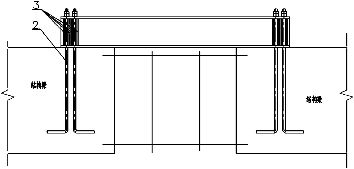
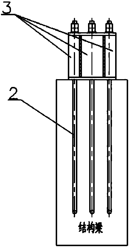
[0029] The construction method of the synchronous removal of the lower formwork system of the telescopic post-cast belt and the surrounding formwork support disclosed in the present invention includes the following steps:

[0030] (1) A steel structure bearing member is installed on the upper part of each post-span cast belt beam;

[0031] (2) Deepening design of load-bearing members and embedded bolts of steel structure, including bolt design of load-bearing members of steel structure;

[0032] In the design of the steel structure bearing member of the present invention, since the post-cast belt is usually placed at 1 / 3 of the beam span, the bending moment and shear force borne by the steel structure bearing member here can be the same as the original structural beam without installation. The value of the internal force when pouring the belt. The load-bearing members of steel structures are checked according to the bending members according to GB50017-2003 "Code for Design of Steel...


PUM


Abstract

The invention discloses a construction method for synchronous dismantling of a lower formwork frame system and a peripheral formwork support of a retractable post-pouring belt. The construction methodcomprises the following steps that cambering is conducted according to the standard when beam end formworks on the two sides of the post-pouring belt are mounted; in-beam steel bars and in-plate steel bars are bound to form a steel bar frame; high-strength bolts are pre-embedded at the ends, at the in-beam steel bars, of the post-pouring belt, and the upper ends of the high-strength bolts stretchout of the upper side of the steel bar frame; concrete is poured, the beam tops are leveled before initial set of the concrete; after the concrete is cured to be qualified, steel structure bearing members are connected to the positions, on the two sides of the post-pouring belt, of the beam end top faces through the pre-embedded high-strength bolts; and the lower formwork frame system and the peripheral formwork support of the post-pouring belt are dismantled. In the construction process of beams and floors on the two sides of the retractable post-pouring belt, the structure bearing members are mounted in the positions, on the two sides of the post-pouring belt, between the beam end top faces through the pre-embedded high-strength bolts, the structure bearing members replace original structural beams to bear the shearing force and torque at the post-pouring belt, and therefore, when the peripheral formwork support of the post-pouring belt is dismantled, the lower formwork frame systemof the post-pouring belt can be dismantled synchronously.

Description

Technical field [0001] The invention belongs to the field of building construction, in particular to a construction method in which a lower formwork system of a telescopic post-cast belt and a peripheral supporting formwork are simultaneously removed. Background technique [0002] According to the requirements of current relevant codes, when the concrete strength of the floor slab reaches the mold removal strength, the lower support formwork of the floor slab can be removed, and the post-casting belt should be closed after the main structure is completed for 60 days and the settlement is stable. Therefore, the lower formwork system of the post-pouring belt must be retained, and cannot be removed together with the lower support formwork of the surrounding floor slab, nor should it be dismantled and then topped, so as to avoid uneven settlement and affect the structural safety. [0003] The dismantling time of the lower formwork system of the post-cast belt and the lower support form...

Claims


Application Information

Patent Timeline
Patent Type & Authority Applications(China)
IPC IPC(8): E04G19/00
Inventor 周灵次阳晓辉陈富仲黄仁清刘琦江
Owner CHINA CONSTR FIFTH ENG DIV CORP LTD
Learn More