A balanced type Roots vacuum pump system and a control method thereof

A Roots vacuum pump, balanced technology, applied in the direction of pumps, pump components, rotary piston pumps, etc., can solve the problems of non-interchangeable use, poor versatility, and reduced effective pumping volume, so as to achieve convenient use and maintenance, and improve Stable and reliable, wide range of effects

Pending Publication Date: 2018-01-09
GUANGDONG KENFLO PUMP CO LTD
View PDF0 Cites 4 Cited by
  • Summary
  • Abstract
  • Description
  • Claims
  • Application Information

AI Technical Summary

Problems solved by technology

Although the air-cooled Roots vacuum pump can improve the heat resistance of the Roots vacuum pump, the backflow of the gas will reduce the pumping efficiency of the Roots pump, and to realize the sealing of the return port when the rotor pumps air, the rotor volume must be required.

Method used


Image

  • A balanced type Roots vacuum pump system and a control method thereof
  • A balanced type Roots vacuum pump system and a control method thereof

Examples


Embodiment 1

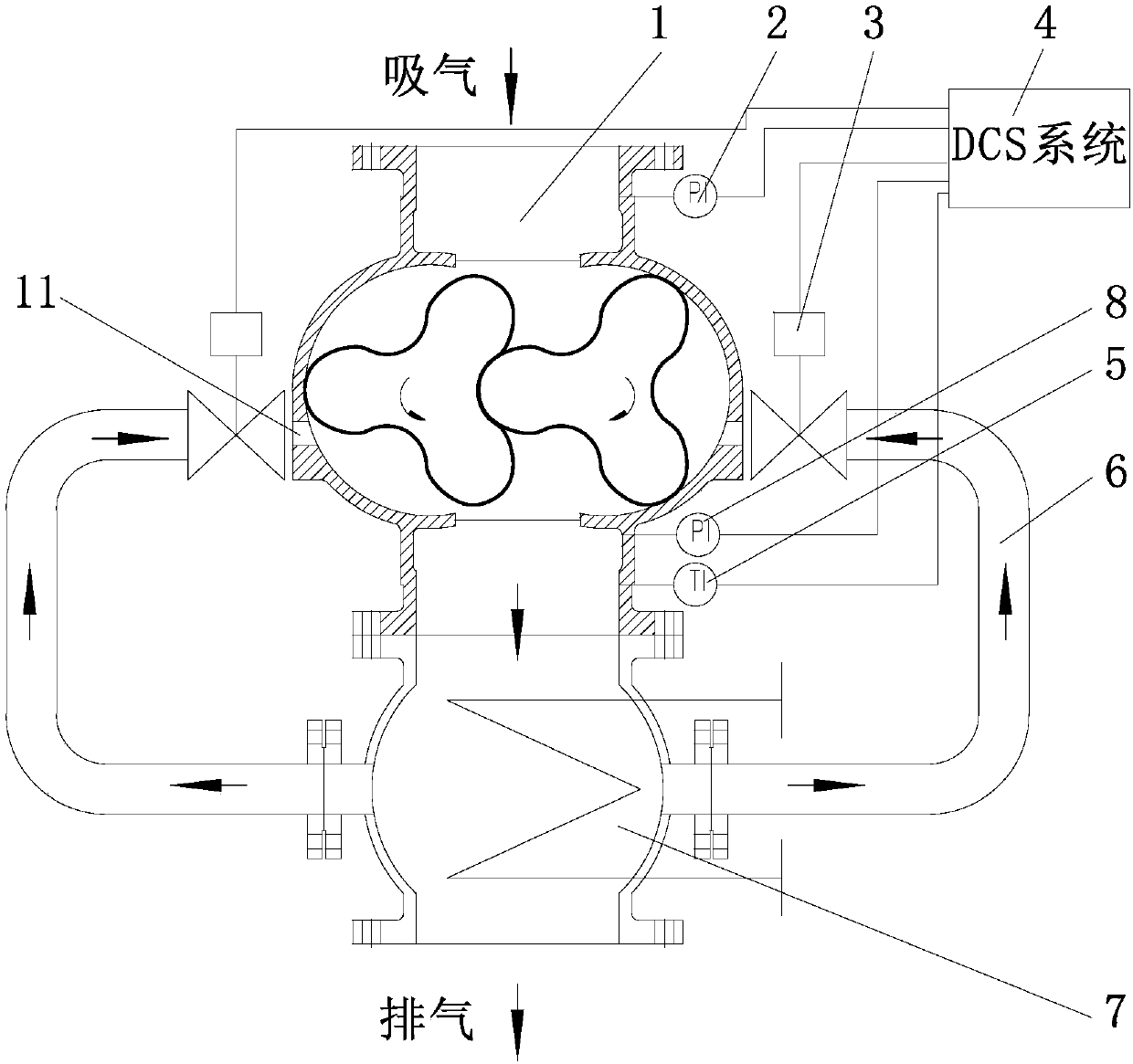
[0040] Such as figure 1 A balanced Roots vacuum pump system shown includes a Roots vacuum pump 1, a condenser 7, a detection mechanism and a DCS system 4; the two sides of the pump body of the Roots vacuum pump 1 are respectively provided with return ports 11, and the return ports 11 are An automatic regulating valve 3 is installed; the condenser 7 is arranged on the air outlet of the Roots vacuum pump 1, and the condenser 7 and the return port 11 are connected by a pipeline 6; the detection mechanism includes a pressure sensor a2, a pressure sensor b8 and a temperature sensor 5 , the pressure sensor a2 and the pressure sensor b8 are arranged on the intake pipeline and the discharge pipeline of the Roots vacuum pump 1 respectively, and the temperature sensor 5 is arranged on the discharge pipeline of the Roots vacuum pump 1 .

[0041] The DCS system 4 includes an input module, an output module, a storage module and a processor; the input module is electrically connected to the...

Embodiment 2

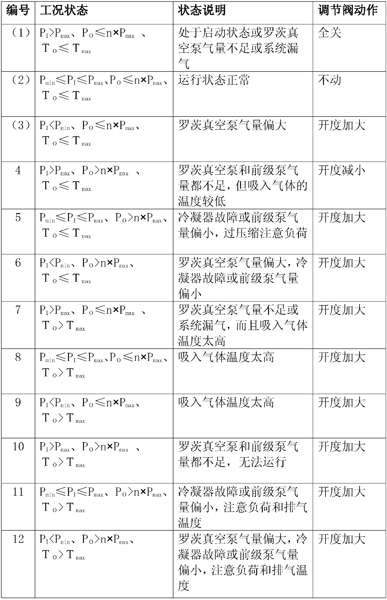
[0052] In this embodiment, the allowable range of gauge suction pressure required by the vacuum system is 40-60mbar(A), the compression ratio of Roots vacuum pump 1 is 3, the limit exhaust temperature is 100°C, and the duration of the abnormal state is allowed to be set. t = 10 minutes, ie P min =40mbar, P max =60mbar, n=3, T max = 100°C.

[0053] First, input the above predetermined value into the DCS system 4, and the system is controlled through the following steps.

[0054] S1, pressure sensor and temperature sensor 5 put the inlet pressure P of Roots vacuum pump 1 I , outlet pressure P 0 and outlet exhaust temperature T o are all transmitted to the DCS system 4;

[0055] S2. The DCS system 4 compares the received data with the set value to determine which state the balanced Roots vacuum pump system is in. For example, when the Roots vacuum pump 1 is just started, the system state is numbered (1);

[0056] S3. The DCS system 4 sends a signal to the automatic regulat...


PUM


Abstract

The invention relates to the technical field of Roots vacuum pumps, particularly a balanced type Roots vacuum pump system. The system includes a Roots vacuum pump, a condenser, a detection mechanism and a DCS system. Two sides of a pump body of the Roots vacuum pump are provided with flow return ports respectively, the flow return ports are provided with automatic adjusting valves. The condenser is disposed at a gas outlet of the Roots vacuum pump. The condenser is connected to each flow return port with a pipeline. A pressure sensor a and a pressure sensor b are disposed on a gas feeding pipeline and a discharging pipeline of the Roots vacuum pump respectively. A temperature sensor is disposed at the discharging pipeline of the Roots vacuum pump. The balanced type Roots vacuum pump systemcan be used as a common Roots vacuum pump and an air-cooled Roots pump, is high in universality and wide in application range, integrates advantages of the two types of Roots pumps, can supply a large amount of air in a situation that a large amount of air is needed, and can supply a large pressure difference when a large pressure difference is needed. A controlling method of the balanced type Roots vacuum pump system is also provided.

Description

technical field [0001] The invention relates to the technical field of Roots vacuum pumps, in particular to a balanced Roots vacuum pump system and a control method thereof. Background technique [0002] Roots vacuum pumps can be divided into three categories according to their uses. One is ordinary Roots vacuum pumps, which are widely used in vacuum smelting, vacuum coating, vacuum impregnation, pharmaceutical chemical industry, aerospace simulation and other fields; the other is air-cooled The Roots vacuum pump uses the cooled gas or the atmosphere to directly cool the rotor, which improves the heat resistance of the Roots vacuum pump, so it is suitable for high temperature, high compression ratio and high pressure difference and other working conditions that ordinary Roots vacuum pumps cannot withstand, such as some electricity and The petrochemical industry; the third is the wet (water-cooled) Roots vacuum pump. This type of vacuum pump directly sprays a small amount of ...

Claims


Application Information

Patent Timeline
IPC IPC(8): F04C28/24F04C28/28F04C18/12F04C29/04
Inventor 陈首挺徐世誉李松峰
Owner GUANGDONG KENFLO PUMP CO LTD
Why Eureka
Try Eureka