
Suspension mechanical mixing device and mixer adopting same

A technology of mechanical mixing and mixing devices, which is applied in the preparation of test samples, etc., can solve the problems of unclean air bubble detection, difficult processing, and difficult removal of small air bubbles, so as to reduce the complexity of the instrument and improve the mixing effect , the effect of not easy to carry pollution

Pending Publication Date: 2018-01-09
孔治
View PDF9 Cites 1 Cited by
  • Summary
  • Abstract
  • Description
  • Claims
  • Application Information

AI Technical Summary

Problems solved by technology

There is a stirring plate inside the bottle, and there must be a gear structure and a transmission mechanism on the outside. The structure is complex, difficult to process, and high in cost. It can only be used for reagent bottles.
[0004] 2. Adding a mechanical stirring rod requires adding a stirring mechanism and a cleaning mechanism. The cost is high, and the cleaning residue is easy to cause pollution
[0006] 4. Ultrasonic stirring, the ultrasonic waves emitted by the ultrasonic transmitter generate a driving force to stir the liquid, the ultrasonic transmitter has a complex structure and high cost, the ultrasonic transducer will attenuate and the replacement cost is high, a transfer medium is required, and the reaction cup or reagent bottle needs to be soaked In the solution, the energy of the ultrasonic mixing process is relatively large, and the bubbles generated will damage the biologically active substances. The bubbles generated during the process will not be drained cleanly in a short time, which will interfere with the detection.
[0007] 5. The remote mixer in the machine oscillates as a whole, requiring a mechanical arm to grab the reagent bottle or reaction cup to the mixer. The mechanical structure is complex, the cost is high, and the time extension affects the speed of the instrument.
[0008] 6. The overall upside-down mixing can only be realized by closing the lid, and the lid opening mechanism or puncture to take samples or reagents is required, which is slow, costly, and easy to pollute
[0009] 7. The overall small-scale vibration and mixing in the machine, the small-scale is difficult to fully mix, it needs to be mixed manually and added to the instrument to let it continue to vibrate, the mixing effect is not good for deeper liquids or slender containers
[0010] 8. Manually placed on the mixer outside the machine to mix, the process is cumbersome, and it is impossible to realize large-scale automatic operation
[0011] Manual oscillation and mixing outside the machine, the process is cumbersome, and it is impossible to realize large-scale automatic operation
[0012] The injection needle blows and mixes evenly, and the speed is slow, which is easy to cause cross-contamination. Small air bubbles are difficult to remove during the blowing process, which will interfere with the subsequent detection.

Method used


Image

  • Suspension mechanical mixing device and mixer adopting same
  • Suspension mechanical mixing device and mixer adopting same
  • Suspension mechanical mixing device and mixer adopting same

Examples


Embodiment 1

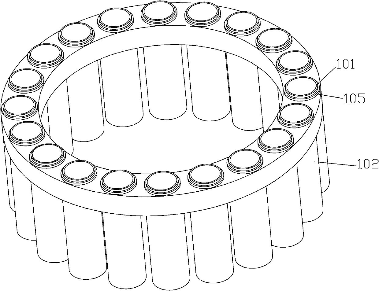
[0038] Embodiment one: see Figure 1-2 .

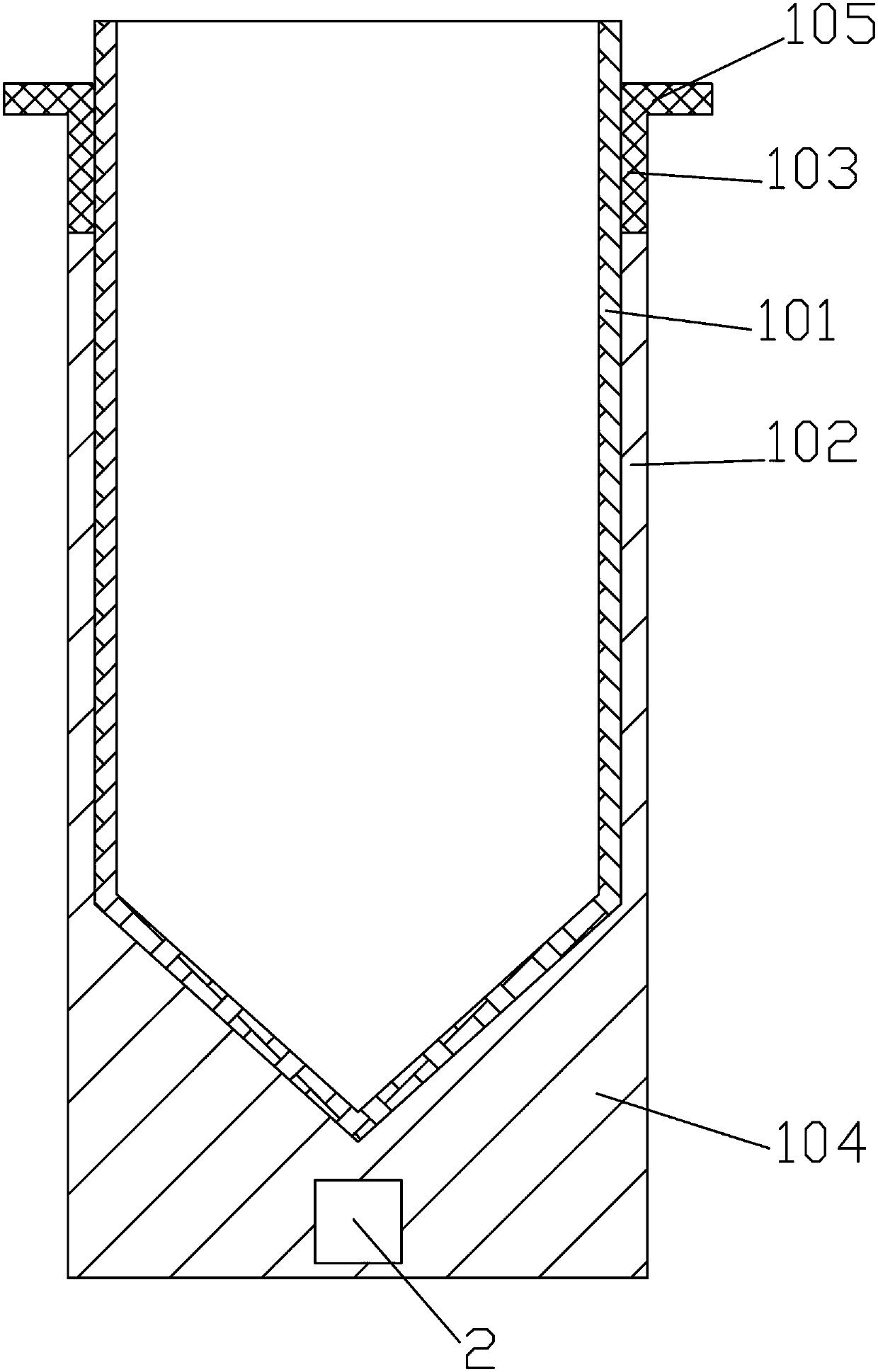
[0039] The invention discloses a suspension mechanical mixing device, which includes an oscillating mixing device 1, the oscillating mixing device includes an oscillating tube 102 for placing a mixing tube 101, the inner wall of the oscillating tube 102 is in contact with the outer wall of the mixing tube 101 Matching, the upper part of the oscillating tube 102 is provided with a flexible tissue 103 for connecting with the external support, the flexible tissue can also have a positioning ring 105 extending outward, and one or more than three The vibration mechanism 2.

[0040] Principle of use of the present invention:

[0041] First, pour the solution to be mixed into the mixing tube 101, turn on the power, and the vibrating mechanism 2 at the bottom of the oscillating tube 102 is energized to vibrate, and because the oscillating tube 102 matches the outer wall of the mixing tube 101, the force generated by the vibration is transmi...

Embodiment 2

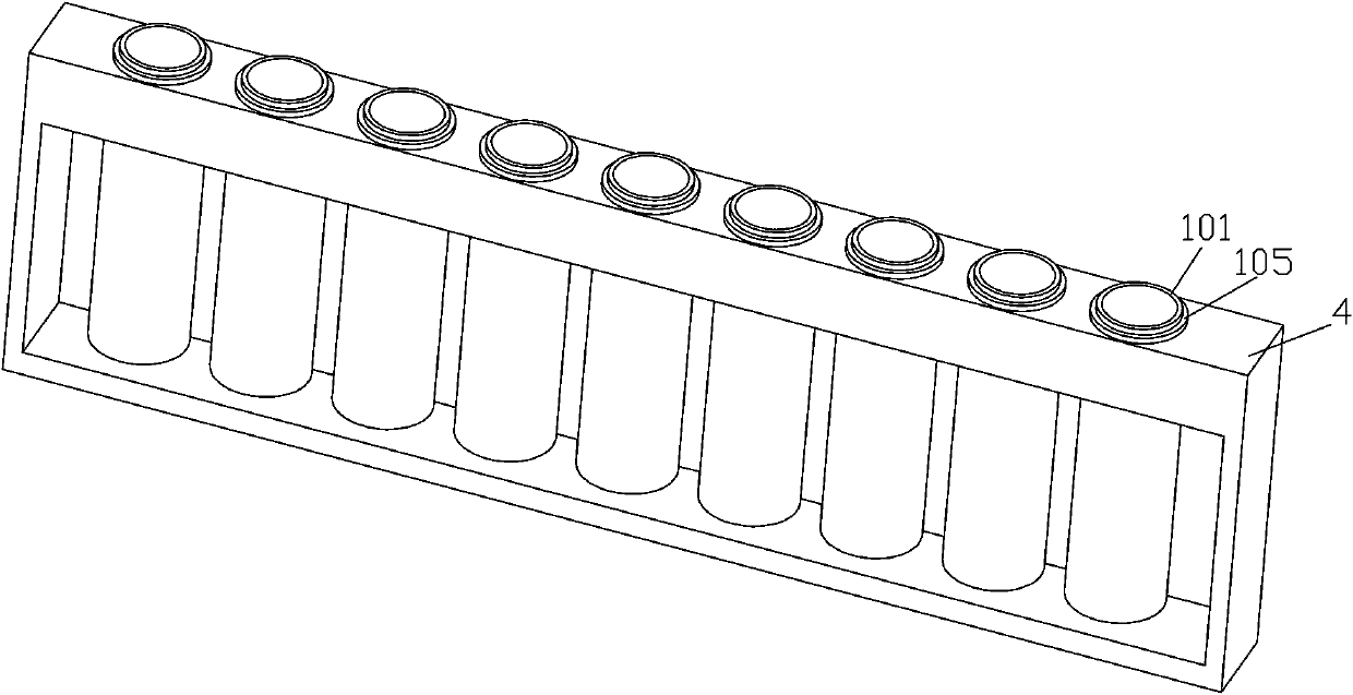
[0048] Embodiment two: see image 3 .

[0049] The same as Embodiment 1 will not be described in detail. The difference is that in this embodiment, the mixing devices are arranged in a linear array, and each mixing device 1 is inserted into a linear sampling mechanism 4. The sampling The mechanism 4 is provided with a row of through holes, and the through holes are used for plugging and fitting with the flexible tissue 103. The positioning ring 105 is located outside each through hole. Similarly, the flexible tissue 103 is inserted tightly between the through holes. An interference fit of extrusion deformation can be used. At the same time, a row of blind holes is provided at the bottom of the sampling mechanism 4 , and the bottoms of the mixing tubes are arranged above the blind holes without contacting them. The linear array is arranged in the sample feeding mechanism 4, and the sample feeding mechanism 4 is driven by an external force to translate to a preset position.

Embodiment 3

[0050]Embodiment three: see Figure 4 .

[0051] The same parts as those in Embodiment 1 will not be described in detail. The difference is that the circular array includes more than two layers, and the mixing devices of each adjacent layer are arranged alternately. In this embodiment, two layers of circular arrays are set up.


PUM


Abstract

The invention relates to the technical field of liquid mixing, and particularly relates to a suspension mechanical mixing device. The device comprises an oscillation mixing device, wherein the oscillation mixing device comprises an oscillation tube for placing a mixing tube, and the inner wall of the oscillation tube is matched with the outer wall of the mixing tube. The device is characterized inthat a flexible tissue connected with an external bracket is arranged at the upper part of the oscillation tube; one or more vibration mechanism is arranged at the bottom of the inner cavity of the oscillation tube. The device can be used for quickly and effectively realizing uniform distribution of suspensions, such as a sample or reaction reagent, for a long time, and has the advantages of simple structure, low cost, good uniform mixing effect, no occurrence of pollution carrying, low failure rate and the like.

Description

technical field [0001] The invention relates to the technical field of liquid mixing, in particular to a suspension mechanical mixing device, and discloses a mixer using the mixing device. Background technique [0002] Currently used in the sample detection process, in order to ensure that the suspension in the sample or reagent does not settle for a long time, or to ensure that the suspension can be fully mixed during the detection process, it is necessary to continuously stir the sample or reagent to achieve a uniform state. The technical means to realize it are as follows: [0003] 1. The inner wall of the reagent bottle or reaction vessel is equipped with a stirring plate, which is driven by an external mechanism to rotate, and the protruding stirring plate on the inner wall plays a role in mixing. There is a stirring plate inside the bottle, and a gear structure and a transmission mechanism on the outside. The complex structure is difficult to process and high cost, so...

Claims


Application Information

Patent Timeline
Patent Type & Authority Applications(China)
IPC IPC(8): G01N1/38G01N1/28
Inventor 孔治
Owner 孔治
Learn More