
Visual adjusting device for debugging photoelectric receiver optical shaft and mechanical shaft

A technology of photoelectric receiver and adjustment device, applied in the direction of coupling of optical waveguides, etc., can solve the problems of harsh working environment, high height of micrometer eyepiece, low working efficiency, etc., to improve working environment, improve economic efficiency, improve The effect of work efficiency

Pending Publication Date: 2018-01-09
XIAN NORTH ELECTRO OPTIC TECH DEFENSE
View PDF19 Cites 1 Cited by
  • Summary
  • Abstract
  • Description
  • Claims
  • Application Information

AI Technical Summary

Problems solved by technology

[0006] 1. Due to the high height of the micrometer eyepiece of the objective lens adjustment device, there are certain difficulties in the assembly and adjustment of the personnel involved in the assembly.
[0007] 2. When observing the reflective imaging of the photosensitive surface of the photoelectric receiver in the micrometer eyepiece, long-term observation is easy to visual fatigue, which will easily lead to a decrease in the accuracy of assembly and adjustment and low labor efficiency, and there will be damage to the eyesight of the assembly personnel and Poor working environment
[0008] 3. The position of the exit pupil (eye point) of the objective lens adjustment device is far from the installation position of the photoelectric receiver on the objective lens adjustment device. When adjusting the optical axis of the photoelectric receiver and the coaxiality of the mechanical axis, it is impossible to achieve simultaneous Observation and simultaneous adjustment
Therefore, in actual operation, it is necessary to repeatedly press the line to measure the reading, remove and adjust the screw stop, and then install the repeated work process of the line pressing reading measurement. There is a phenomenon of cumbersome operation, time-consuming and laborious, resulting in low work efficiency and affecting photoelectric reception. The speed of device installation and adjustment is difficult to guarantee the shift production

Method used


Image

  • Visual adjusting device for debugging photoelectric receiver optical shaft and mechanical shaft
  • Visual adjusting device for debugging photoelectric receiver optical shaft and mechanical shaft
  • Visual adjusting device for debugging photoelectric receiver optical shaft and mechanical shaft

Examples


Embodiment 1

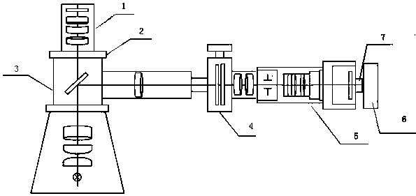
[0033] Such as image 3 As shown, a visual adjustment device for adjusting the optical axis and mechanical axis of a photoelectric receiver includes an objective lens adjustment device 3, an image observer 5 and an LED display 6, and one end of the image observer 5 is adjusted with the objective lens through a connector 12 The device 3 is fixedly connected, and the other end of the image observer 5 is electrically connected to the LED display 6 through the power interface 7 .

Embodiment 2

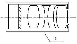
[0035] On the basis of Example 1, such as Figure 4 Shown, described image observer 5 is made up of CCD circuit board, objective lens holder 9 and image observer objective lens group 10; One end of objective lens holder 9 is fixed with image observer objective lens group 10, and the other end is fixed with CCD circuit board 8, The CCD circuit board 8 is provided with a regulated power supply, and the regulated power supply is electrically connected to the LED display 6 through the power interface 7 .

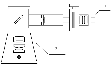
[0036] The image observer 5 is installed in the connector 12 , and the image observer objective lens group 10 is located at the exit pupil 11 of the measuring microscope 4 .

[0037] The image observer objective lens group 10 is composed of a convex lens and a concave lens, the end close to the CCD circuit board is a concave lens, and the end far away from the CCD circuit board is a convex lens.

Embodiment 3

[0039] On the basis of Example 2, such as Figure 5a and Figure 5b As shown, the objective lens holder 9 is a cylindrical body 91, one end of the cylindrical body is provided with a rectangular frame 92, and a fixing hole 93 is provided on the rectangular frame. The objective lens group 10 of the image observer is socketed on the cylindrical body 91 of the objective lens holder 9, and is fixed by dispensing glue, so as to avoid the displacement of the objective lens, resulting in blurred images, and the repeated work of readjustment. The objective lens holder 9 is fixed in the connector 12 through the fixing hole 93 on the rectangular frame 92 .

[0040] Such as Figure 6a and Figure 6b As shown, the connector 12 is a rectangular body with a cavity, the cavity is arranged along the length direction of the rectangular body, and the two ends of the cavity are large and the middle is small. The rectangular design of the connector makes it sit smoothly and ensures the accura...


PUM


Abstract

The invention relates to a visual adjusting device for debugging a photoelectric receiver optical shaft and a mechanical shaft, which comprises an objective lens timing device. The visual adjusting device is characterized by further comprising an image observer and an LED displayer; one end of the image observer is fixedly connected with the objective lens timing device through a connector, and the other end thereof is electrically connected with the LED displayer through a power interface. The visual adjusting device has the advantages of the visualization of coaxial mounting and debugging ofthe optical shaft and the mechanical shaft of an optical spare part in the photoelectric receiver, reducing the vision impairment of regulators by light intensity, improving the labor working environment, improving the adjusting efficiency, and lightning the labor intensity of the adjusting staffs. Besides, the visual adjusting device reaches the purpose of improving both working efficiency and economic benefit.

Description

technical field [0001] The invention relates to an adjustment device, in particular to a visual adjustment device for adjusting the optical axis and mechanical axis of a photoelectric receiver. Background technique [0002] The photoelectric receiver is a device that can convert optical radiation energy into electrical signals, so as to obtain the laser echo signal emitted by the laser irradiator after diffuse reflection of the destroyed target, and complete the stabilization, search and tracking of the destroyed target. [0003] At present, the domestic photoelectric receiver is composed of an objective lens system composed of multiple sets of optical lenses and a photoelectric detector. The accuracy of the focal length of the objective lens is realized by adjusting the dispersion circle, and then the optical axis of the photoelectric receiver ( The connection between the centers of all the lenses that make up the optical system) and the coaxiality of the mechanical axis (r...

Claims


Application Information

Patent Timeline
Patent Type & Authority Applications(China)
IPC IPC(8): G02B6/42
Inventor 闫博李东奇梁小伟任航
Owner XIAN NORTH ELECTRO OPTIC TECH DEFENSE
Learn More