
Chip packaging structure and packaging method

A chip packaging structure and chip packaging technology, applied in the manufacturing of electrical components, electrical solid-state devices, semiconductor/solid-state devices, etc. Enhanced sealing performance and guaranteed miniaturization

Active Publication Date: 2018-01-09
NAT CENT FOR ADVANCED PACKAGING
View PDF3 Cites 0 Cited by
  • Summary
  • Abstract
  • Description
  • Claims
  • Application Information

AI Technical Summary

Problems solved by technology

[0004] The above-mentioned packaging technology has the following defects: 1. The power chip is arranged on the surface of the rewiring layer through a plurality of micro-bumps. On the one hand, the setting of the micro-bumps increases the thickness of the entire packaging structure to a certain extent. For power-consuming chips with certain space requirements, extra space needs to be provided for them, for example, by increasing the height of micro-bumps, etc., which will undoubtedly greatly increase the thickness of the package structure, which is not conducive to the miniaturization of the package volume; 2 , The outer surface of the power chip is exposed, the sealing is poor, the power chip is easily damaged, and the reliability is greatly reduced

Method used


Image

  • Chip packaging structure and packaging method
  • Chip packaging structure and packaging method
  • Chip packaging structure and packaging method

Examples


Embodiment 1

[0045] This embodiment provides a chip packaging method, comprising the following steps:

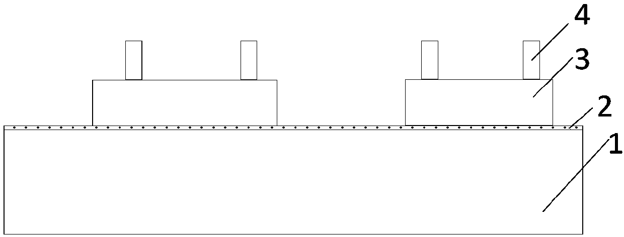
[0046] Step S1 , disposing a plurality of first chips 3 on the carrier 1 . Wherein, the first chip 3 is not limited to one kind of chip, and may be various or not all the same kind of chips.

[0047] As an implementation manner of this embodiment, step S1 specifically includes the following steps:

[0048] Step S11, providing a carrier 1, which is generally a silicon slide;

[0049] Step S12, forming an adhesive layer 2 on the carrier 1, specifically, spin-coating a photosensitive temporary bonding glue, such as UV glue, etc. on the carrier 1 by spin coating;

[0050] Step S13 , affixing each first chip 3 on the adhesive layer 2 on the carrier 1 through a patching process, and the first chips 3 are arranged in a matrix.

[0051] Step S2, setting a plurality of first connecting posts 4 on the electrodes of the first chip 3, the first connecting posts 4 are arranged on the side of the f...

Embodiment 2

[0074] This embodiment provides a chip packaging structure, including a first package body 5 and a second package body 11 .

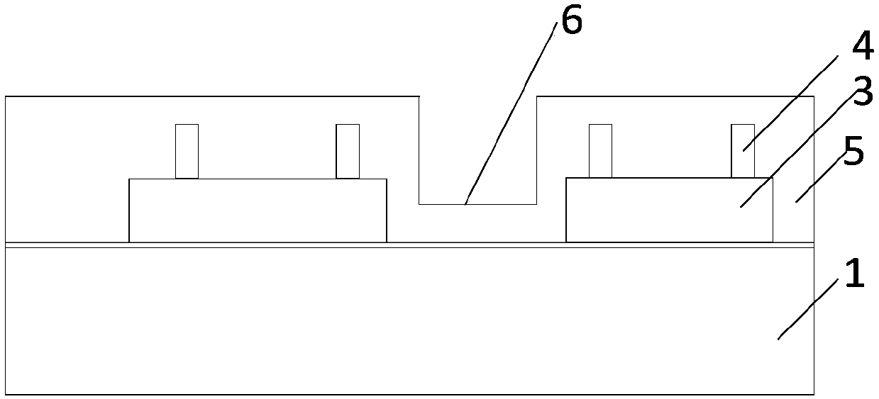
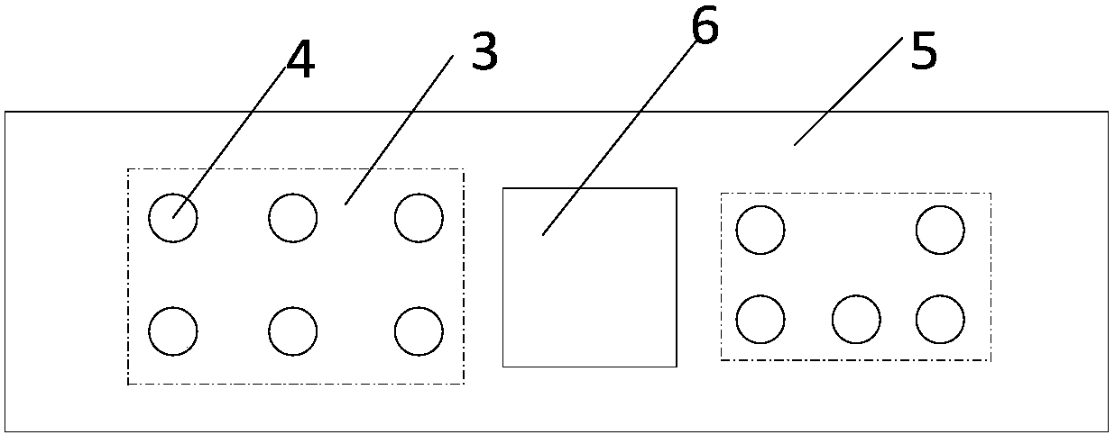
[0075] A plurality of first chips 3 are disposed in the first package 5 , and a groove 6 is provided on the first package 5 between adjacent first chips 3 . Wherein, the first chips 3 are arranged in a matrix, and the first chips 3 are not limited to one kind of chips, but can be various or not all of the same kind of chips, and the groove body 6 is not connected to the adjacent first chips 3 .

[0076] The second package body 11 is directly disposed on the first package body 5 and has a plurality of second chips 8 inside. The second chips 8 are disposed above the slot body 6 and electrically connected to the first chip 3 .

[0077] As an implementation of this embodiment, a wiring layer 7 is also provided on the first package body 5, and a plurality of first connecting posts 4 are provided on the first chip 3, and the wiring layer 7 is connected to the...


PUM


Abstract

The invention, which relates to the field of the chip packaging technology, discloses a chip packaging method. The method comprises the following steps that: a plurality of first chips are arranged ona carrier; the first chips are packaged to form a first packaging body; groove bodies are formed in the parts, between the adjacent first chips, of the first packaging body; and second chips are arranged above the groove bodies and are connected with the first chips electrically. Therefore, on the one hand, with the groove bodies, needed cavities and sealed structures are provided for the secondhips; and on the other hand, the groove bodies are arranged in the formed first packaging body, so that dimensions of packaging structures of several kinds of chips in horizontal and vertical directions are reduced and the miniaturization of the packaging structure is ensured. Besides, the packaging method is simple and is easy to implement.

Description

technical field [0001] The invention relates to the technical field of chip packaging, in particular to a chip packaging structure and a packaging method. Background technique [0002] In the field of integrated circuit chip packaging technology, how to reduce packaging costs and improve production efficiency without affecting chip functions and increasing packaging volume has become a very important and urgent research topic internationally. Stacked chip packaging technology is a new technology that stacks and packages multiple chips of different functions and sizes together. [0003] The prior art discloses a packaging method for a package integrated with a power supply transmission system, which includes the following steps: 1) providing a carrier; 2) using an electroplating process to form a first metal connection post on the surface of the carrier; 3) connecting the active The module and the passive module are arranged on the surface of the carrier on which the first m...

Claims


Application Information

Patent Timeline
IPC IPC(8): H01L21/56H01L21/60H01L23/31H01L23/538
CPCH01L2224/04105H01L2224/12105H01L2224/16227H01L2224/18H01L2224/81005H01L2924/1461H01L2924/15159H01L2924/1815H01L2924/18162
Inventor 任玉龙孙鹏
Owner NAT CENT FOR ADVANCED PACKAGING
Learn More