Branch-line coupler

A coupler and branch line technology, applied in the field of couplers, can solve problems such as large circuit board area, and achieve the effect of small occupied area and good performance

Inactive Publication Date: 2018-01-09
NANNING FUGUI PRECISION IND CO LTD
View PDF1 Cites 4 Cited by
  • Summary
  • Abstract
  • Description
  • Claims
  • Application Information

AI Technical Summary

Problems solved by technology

However, traditional 3dB branch line coupl

Method used


Image

  • Branch-line coupler
  • Branch-line coupler
  • Branch-line coupler

Examples


Embodiment Construction

[0043] The specific parameters of the following embodiments are only for better illustrating the present invention, but should not limit the scope of the claims of the present invention with specific numerical values.

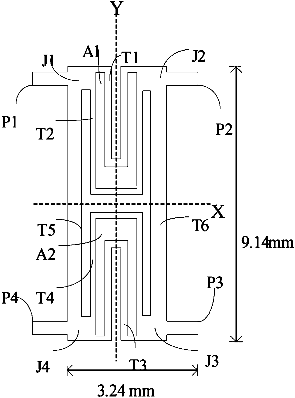
[0044] see figure 2 , figure 2 It is a structural diagram of an embodiment of the branch line coupler of the present invention. In this embodiment, the branch line couplers of the present invention are respectively symmetrical about the X axis and the Y axis, that is, the branch line couplers are respectively symmetrical about the center lines of the two sides. The branch line coupler of the present invention includes a first port P1, a second port P2, a third port P3, and a fourth port P4, the first meander-shaped transmission line T1, the second meander-shaped transmission line T2, and the third meander-shaped transmission line T3 and the fourth meander-shaped transmission line T4, the first strip-shaped transmission line T5 and the second strip-shaped tra...


PUM


Abstract

A branch-line coupler suitable for use in mobile devices includes a first, second, third, and fourth ports, respectively acting as input, transmitted, coupled, and isolated port. A first, second, third, and fourth connection parts are connected to the ports and transmission lines. First and second bent transmission lines are electrically connected between first and second ports. Third and fourth bent transmission lines are electrically connected between third and fourth ports. A first long strip transmission line is electrically connected between the first port and the fourth port. A second long strip transmission line is electrically connected between the second port and the third port. The branch-line coupler occupies a small area and has high performance.

Description

technical field [0001] The invention relates to a coupler, in particular to a 3dB branch line coupler. Background technique [0002] It is well known that in many microwave circuits, directional couplers are often used to solve the related problems caused by distributing power. With the development of mobile communication technology and satellite communication technology, in order to facilitate portability and mobility, the miniaturization of communication equipment is becoming more and more important. [0003] Branch line couplers are widely used in microwave integrated circuits and monolithic integrated circuits. Traditional branch line couplers, such as 3dB branch line couplers, are composed of four quarter-wavelength transmission lines, figure 1 It is a structural schematic diagram of a traditional 3dB branch line coupler, such as figure 1 The traditional drop line coupler shown is 7.4 millimeters (mm) long and 9.14 millimeters (mm) wide. However, conventional 3dB br...

Claims


Application Information

Patent Timeline
IPC IPC(8): H01P5/12H01P5/18
CPCH01P5/227
Inventor 阙郁智
Owner NANNING FUGUI PRECISION IND CO LTD
Why Eureka
Try Eureka