
Monitoring system and monitoring method of SR4 optical module transmitting power

A monitoring system and transmission power technology, applied in the transmission system, electromagnetic wave transmission system, electrical components, etc., can solve problems such as failure, and achieve the effect of easy operation, easy maintenance, and simple structure

Pending Publication Date: 2018-01-09
O NET COMM (SHENZHEN) LTD
View PDF0 Cites 1 Cited by
  • Summary
  • Abstract
  • Description
  • Claims
  • Application Information

AI Technical Summary

Problems solved by technology

However, this method will fail as the SR4 optical module ages and changes in temperature

Method used


Image

  • Monitoring system and monitoring method of SR4 optical module transmitting power
  • Monitoring system and monitoring method of SR4 optical module transmitting power
  • Monitoring system and monitoring method of SR4 optical module transmitting power

Examples


Embodiment Construction

[0029] Now in conjunction with the accompanying drawings, the preferred embodiments of the present invention will be described in detail.

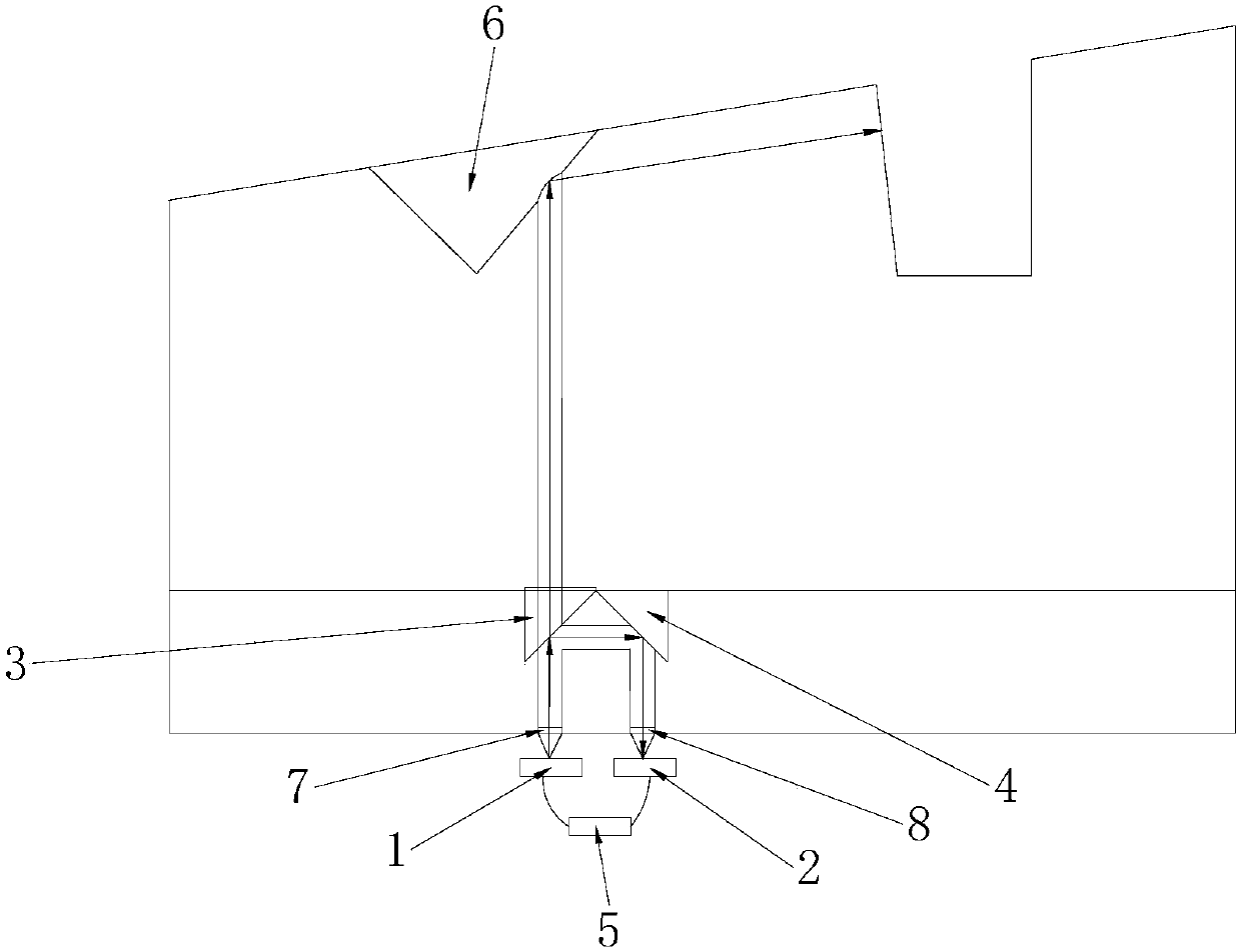
[0030] Such as figure 1 As shown, the present invention provides a preferred embodiment of a monitoring device for transmitting power of an SR4 optical module.

[0031] A monitoring system for transmitting power of an SR4 optical module, comprising a transmitting device 1 and a monitoring device 2, the transmitting device 1 is used to emit an input beam, the monitoring device 2 is used to receive a reflected beam, and the monitoring system also includes a beam splitter The spectroscopic device 3, the first reflection device 4 for reflection and the main control device 5, the main control device 5 is respectively connected to the emission device 1 and the monitoring device 2, and the emission device 1, the monitoring device 2 and the main control device 5 are all Welded on the PCB board to achieve the above functions.

[0032] Specificall...


PUM


Abstract

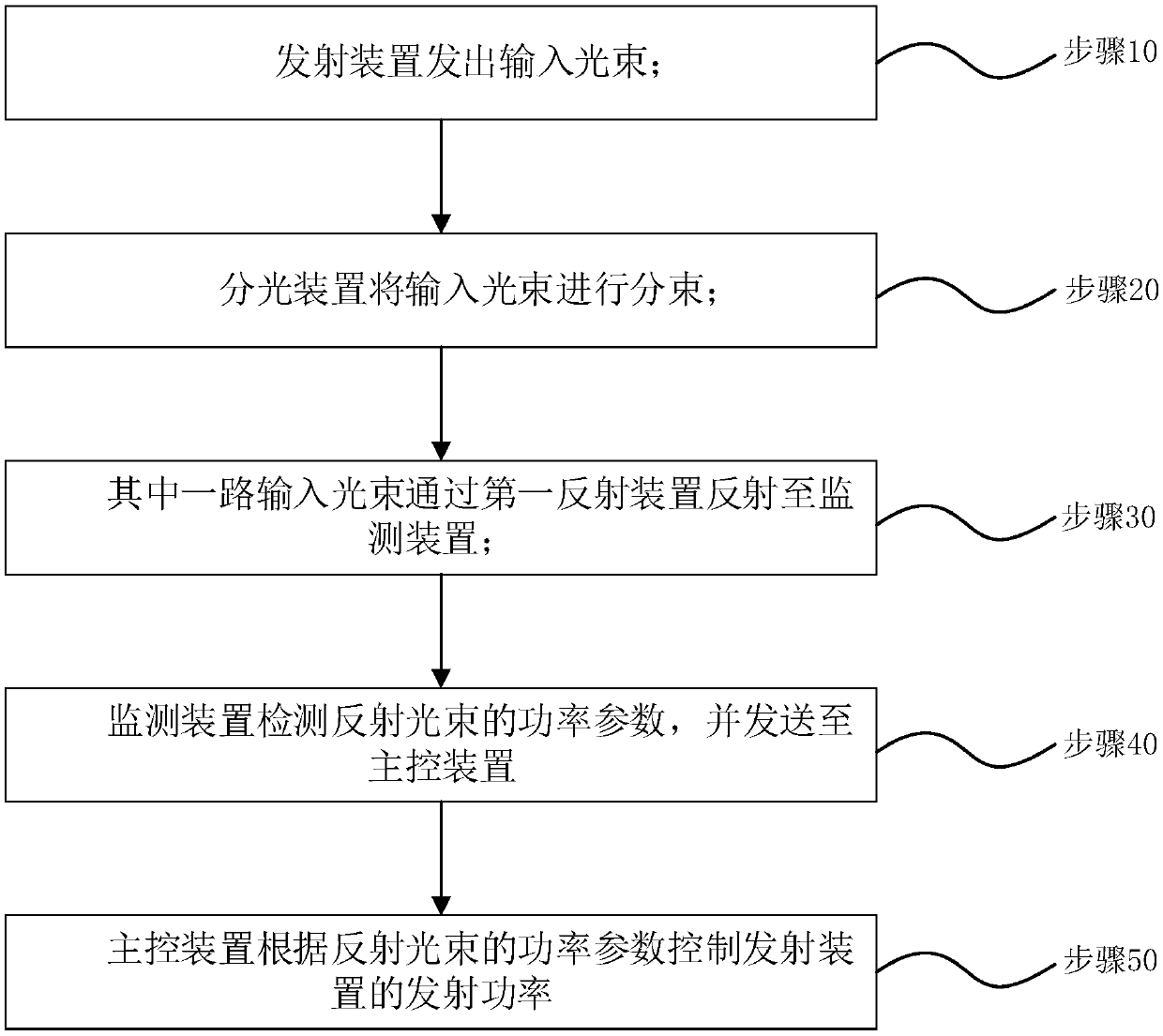
The invention relates to the field of optical transceivers, and in particular to a monitoring system and a monitoring method of SR4 optical module transmitting power. The system comprises a transmitting device, a monitoring device, a light splitting device, a first reflection device and a main control device, the transmitting device sends an input beam to the light splitting device, the light splitting device divides the input beam, a part of input beams is input to the first reflection device and is reflected to the monitoring device by the first reflection device, the monitoring device receives the reflected beam, detects a power parameter of the reflected beam and sends the power parameter of the reflected beam to the main control device, and the main control device controls the transmitting power of the transmitting device according to the power parameter of the reflected beam. According to the monitoring system, optical path splitting and turning are achieved in an SR4 optical module, the transmitted beam is controlled by detecting the reflected beam, direct monitoring of the transmitting power is achieved, and the influence to the monitoring by the device aging or temperaturechange is avoided.

Description

technical field [0001] The invention relates to the field of optical transceivers, in particular to a monitoring system and method for transmitting power of an SR4 optical module. Background technique [0002] At present, unlike people who pay attention to spectral efficiency and distance-bit rate product in long-distance networks, in the internal network of high-throughput data centers, the optical fiber used to connect servers is only a few meters to a few kilometers, and people pay more attention to The intra-site interconnection is realized by means of high-speed short-distance optical fiber modules. [0003] The existing SR4 optical module (4-channel parallel-optical-module for short reachoptical links, 4-channel short-distance optical module), usually adopts the solution of integrating four transceiver chips on the PCB board, and the single-channel rate is 25Gbps, that is, Can achieve up to 100Gbps aggregate rate. In this type of device, the transmitting power of the...

Claims


Application Information

Patent Timeline
Patent Type & Authority Applications(China)
IPC IPC(8): H04B10/071
CPCH04B10/071
Inventor 雷奖清林星
Owner O NET COMM (SHENZHEN) LTD
Learn More