
Energy-saving environment-friendly power generation equipment

A power generation equipment, energy saving and environmental protection technology, applied in the direction of mechanical equipment, engine components, machines/engines, etc., can solve the problems of insufficient reliability performance, affecting the normal operation of generators, affecting the stability and efficiency of power generation of equipment, etc., to improve Reliable performance, guaranteed stability and efficiency

Inactive Publication Date: 2018-01-12
上海瓜齐电子科技有限公司
View PDF1 Cites 0 Cited by
  • Summary
  • Abstract
  • Description
  • Claims
  • Application Information

AI Technical Summary

Problems solved by technology

[0004] Aiming at the deficiencies of the existing technology, the purpose of the present invention is to provide an energy-saving and environment-friendly power generation equipment to solve the problem that the existing technology cannot control the flow path of the coolant in the combustion chamber of the generator during the process of energy-saving power generation, and the coolant cannot maintain the circulating temperature , may affect the normal operation of the generator, affect the stability and efficiency of the power generation work of the equipment, and the problem of insufficient reliability

Method used


Image

  • Energy-saving environment-friendly power generation equipment
  • Energy-saving environment-friendly power generation equipment

Examples


Embodiment Construction

[0018] In order to make the technical means, creative features, goals and effects achieved by the present invention easy to understand, the present invention will be further described below in conjunction with specific embodiments.

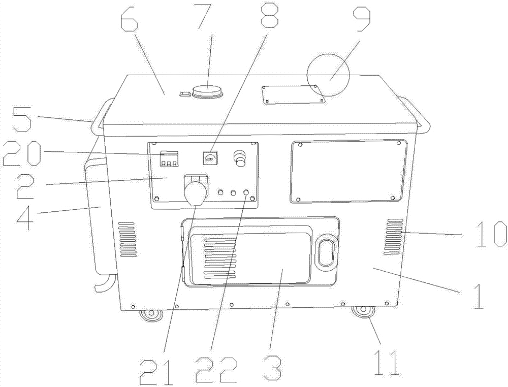
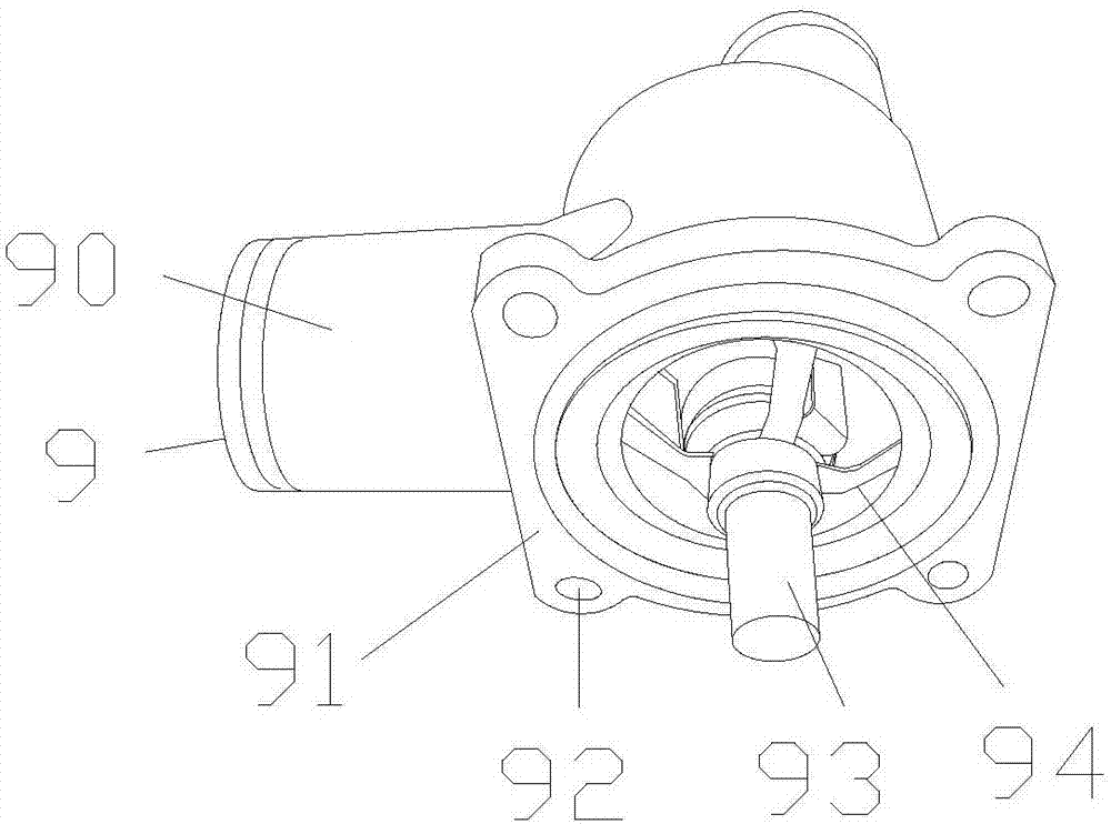
[0019] see Figure 1-Figure 2 , the present invention provides an energy-saving and environment-friendly power generation equipment, the structure of which includes a generator body 1, a control panel 2, a compressor box door 3, a diesel engine cabin door 4, a moving handle 5, a box cover 6, an air pressure sensor 7, a voltmeter 8, and a thermostat 9, the control panel 2 is electrically connected to the front end surface of the generator body 1, the compressor box door 3 is movably connected to the lower part of the front end surface of the generator body 1, and the diesel engine compartment door 4 is movably connected to the left end of the generator body 1 On the surface, the moving handle 5 is fixedly welded to the upper part of the left end su...


PUM


Abstract

The invention discloses energy-saving environment-friendly power generation equipment. The energy-saving environment-friendly power generation equipment structurally comprises a power generator body,a control panel, a compressor casing door, a diesel engine bin door, a movable handle, a case cover, a barometric sensor, a voltage meter and a thermostat, wherein the control panel is electrically connected to the surface of the front end of the power generator body, the compressor casing door is movably connected to the lower portion of the surface of the front end of the power generator body, the diesel engine bin door is movably connected to the surface of the left end of the power generator body, and the movable handle is fixedly welded to the upper portion of the surface of the left endof the power generator body; and the case cover is connected to the surface of the upper end of the power generator body through bolts, the barometric sensor is electrically connected to the surface of the upper end of the case cover, and the voltage meter is electrically connected to the surface of the front end of the control panel. According to the energy-saving environment-friendly power generation equipment, in the energy-saving power generation process, the flowing path of cooling liquid in a combustion chamber of a power generator can be controlled, and thus the circulating temperatureof the cooling liquid can be maintained; and normal operation of the power generator and the operating stability and efficiency of equipment are ensured, and the reliability of the equipment is effectively improved.

Description

technical field [0001] The invention is an energy-saving and environment-friendly power generation equipment, which belongs to the field of electric equipment. Background technique [0002] The power system includes the power grid, power generation equipment and various electrical equipment. Most of the existing power generation equipment adopts coal combustion power generation or nuclear power generation. Coal combustion power generation is to convert the heat energy generated by coal combustion into electrical energy through power generation power devices, such as power plant boilers , steam turbines, generators and their auxiliary devices, etc. However, when coal is burned, it will produce a lot of smoke, causing certain pollution to the environment, and at the same time, it also consumes a lot of energy; nuclear power generation uses the heat released by nuclear fission in nuclear reactors The way to generate electricity consumes a lot of energy. [0003] The prior art ...

Claims


Application Information

Patent Timeline
Patent Type & Authority Applications(China)
IPC IPC(8): F01P7/16F02B63/04
Inventor 贺小玉
Owner 上海瓜齐电子科技有限公司
Learn More