

A vision measurement specular reflection light interference suppression method
A specular reflection and light interference technology, applied in the field of vision measurement, can solve problems such as specular reflection light interference, and achieve the effect of improving robustness and usability
- Summary
- Abstract
- Description
- Claims
- Application Information
AI Technical Summary
Problems solved by technology
Method used
Image

Examples
Embodiment 1
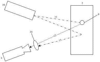
[0018] The light source 10 adopts a 365nm ultraviolet light source, the optical filter 15 selects a 365nm narrow-band optical filter for use, selects green fluorescent powder to make a circular fluorescent artificial marker point 9, the central wavelength of the fluorescent light 12 is 532nm, and the optical filter 14 selects a 532nm narrow-band optical filter for use. The wavelength ranges of the filter 15 and the filter 14 do not overlap.
[0019] After the ultraviolet light emitted by the light source 10 is gated by the filter 15, other colors of light are eliminated, and the spectral energy is concentrated in the vicinity of 365nm. After irradiating the fluorescent powder on the surface of the fluorescent artificial marker point 9, the fluorescent light 12 is radiated outward. The central wavelength of the fluorescent light 12 is 532nm, the filter 14 only passes 532nm fluorescence and cuts off 365nm ultraviolet light, thereby avoiding the specular reflection light generated...
Embodiment 2
[0021] The light source 10 adopts a 280nm ultraviolet light source, the optical filter 15 selects a 280nm narrow-band optical filter for use, selects green fluorescent powder to make a circular fluorescent artificial marker point 9, the central wavelength of the fluorescent light 12 is 532nm, and the optical filter 14 selects a 532nm narrow-band optical filter for use. The wavelength ranges of the filter 14 and the filter 15 do not overlap.
[0022] After the ultraviolet light emitted by the light source 10 is gated by the filter 15, other colors of light are eliminated, and the spectral energy is concentrated around 280nm. After irradiating the fluorescent powder on the surface of the artificially marked 9 points, the fluorescent light 12 is radiated outward. The central wavelength of the fluorescent light 12 is 532nm. , the filter 14 only passes the 532nm fluorescent light 12 and cuts off the 280nm ultraviolet light, thereby avoiding the specular reflection light generated by...
Embodiment 3
[0024] The light source 10 adopts a 365nm ultraviolet light source, the filter 15 selects a 365nm narrow-band filter for use, selects red fluorescent powder to make a circular fluorescent artificial marker point 9, the central wavelength of the fluorescence 12 is 650nm, and the filter 14 selects a 650nm narrow-band filter for use. The wavelength ranges of the optical sheet 14 and the optical filter 15 do not overlap.
[0025] After the ultraviolet light emitted by the light source 10 is gated by the filter 15, other colors of light are eliminated, and the spectral energy is concentrated around 365nm. After irradiating the fluorescent powder on the surface of the fluorescent artificial marker point 9, the fluorescent light 12 is radiated outward. The central wavelength of the fluorescent light 12 is 650nm. , the filter 14 only passes the 650nm fluorescent light 12, and cuts off the 365nm ultraviolet light, thereby avoiding the specular reflection light generated by the specular ...
PUM
 Abstract
Description
Claims
Application Information