
A non-magnetic sensor

A magnetic sensor and inductance technology, applied in the field of meter measurement, can solve the problems of mutual coupling, interference, affecting the realization of non-magnetic sensing function and the accuracy of measurement, and the lack of sufficient space distance for the LC oscillator circuit. The effect of improving accuracy and reducing costs

Active Publication Date: 2020-05-26
CHONGQING SMART METER GRP CO LTD
View PDF10 Cites 0 Cited by
  • Summary
  • Abstract
  • Description
  • Claims
  • Application Information

AI Technical Summary

Problems solved by technology

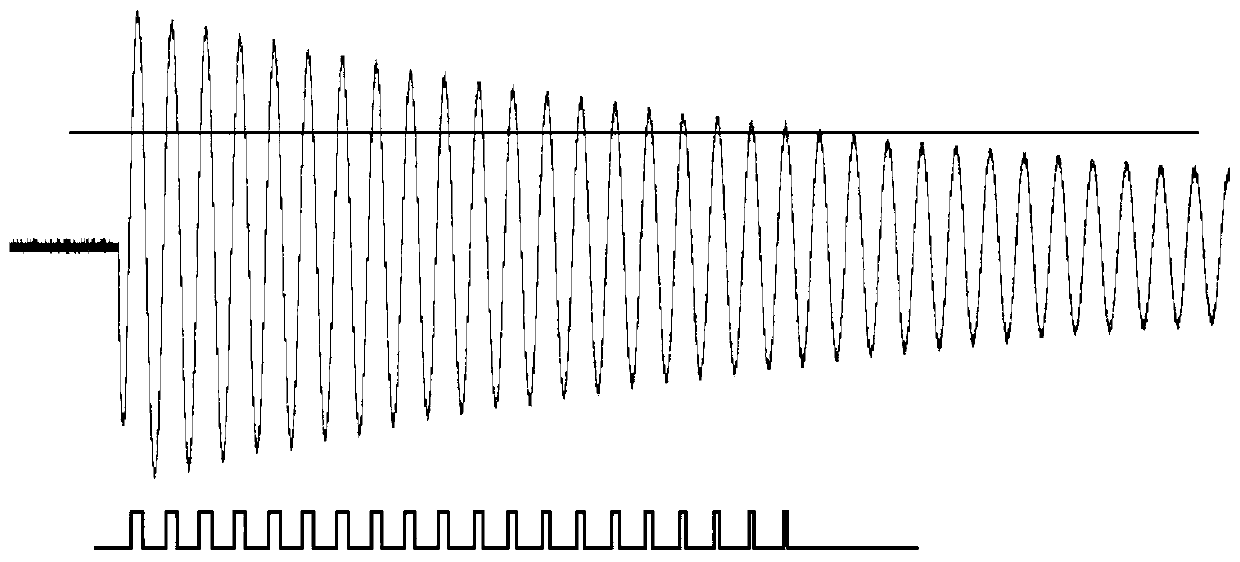
[0005] When this kind of non-magnetic sensor is used in a place with a large layout space, the non-magnetic sensor can be designed to be larger, so that there is enough space between the inductances of each LC oscillating circuit, and avoid mutual coupling and interference between them. However, for some metering instruments (such as small-caliber water meters), due to the limitation of metering meter volume, the arrangement of this non-magnetic sensor will be greatly restricted, and there is not enough space between each LC oscillating circuit. They are easy to form mutual coupling and interference (see Figure 5 , Image 6 ), affecting the realization of the non-magnetic sensing function and the accuracy of measurement

Method used


Image

  • A non-magnetic sensor
  • A non-magnetic sensor
  • A non-magnetic sensor

Examples


Embodiment 1

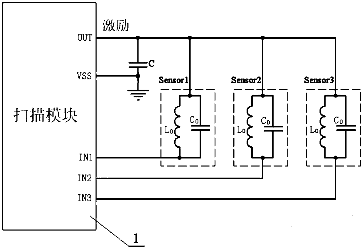
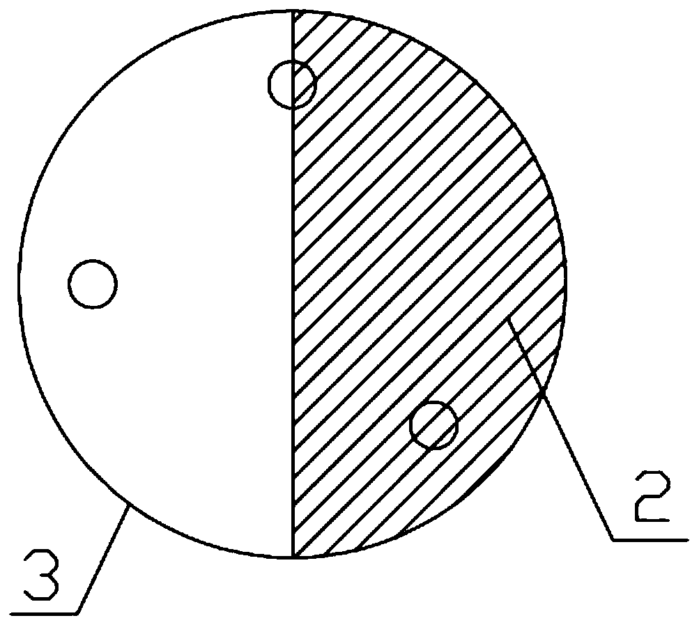
[0031] Embodiment 1: as Figure 7 , Figure 8 The non-magnetic sensor shown includes a scanning module 1, three LC oscillating circuits (namely the first LC oscillating circuit 4, the second LC oscillating circuit 5, and the third LC oscillating circuit 6) and is installed on the upper end of the impeller and on A plastic disc 3 covered with a metal sheet 2 on the surface, the metal sheet 2 is semicircular and covers half of the upper surface of the plastic disc 3 . The first LC oscillator circuit 4 consists of the first capacitor C 1 with the first inductance L 1 Parallel configuration, the resonant angular frequency of the first LC oscillator circuit 4 The second LC oscillator circuit 5 consists of a second capacitor C 2 with the second inductance L 2 Parallel configuration, the resonant angular frequency of the second LC oscillator circuit 5 The third LC oscillating circuit 6 is composed of the third capacitor C 3 with the third inductance L 3 In parallel configur...

Embodiment 2

[0033] Embodiment 2: The structure of the non-magnetic sensor in this embodiment is mostly the same as that of Embodiment 1, the difference is: L 1 ≠ L 2 ≠ L 3 (i.e. the first inductance L 1 , the second inductance L 2 , the third inductance L 3 not equal), C 1 =C 2 =C 3 (i.e. the first capacitor C 1 , the second capacitance C 2 , the third capacitor C 3 equal).

Embodiment 3

[0034] Embodiment 3: The structure of the non-magnetic sensor in this embodiment is mostly the same as that of Embodiment 1, the difference is: L 1 ≠ L 2 ≠ L 3 (i.e. the first inductance L 1 , the second inductance L 2 , the third inductance L 3 not equal), C 1 ≠C 2 ≠C 3 (i.e. the first capacitor C 1 , the second capacitance C 2 , the third capacitor C 3 not equal).


PUM


Abstract

The invention discloses a non-magnetic sensor which comprises a scanning module, a plurality of LC oscillating circuits and a plastic disc. The LC oscillating circuits are electrically connected withthe scanning module, the plastic disc is mounted at the upper end of an impeller, sheet metal covers a part of the upper surface of the plastic disc, inductors of the LC oscillating circuits directlyface the plastic disc and are arranged above the plastic disc, and the various LC oscillating circuits have unequal resonant angular frequencies. The non-magnetic sensor has the advantages that the various LC oscillating circuits are free of interference on one another in limited spaces, the non-magnetic sensor has non-magnetic sensing functions, and the measurement accuracy can be improved.

Description

technical field [0001] The invention belongs to the technical field of meter measurement, and in particular relates to a non-magnetic sensor which can be used for metering. Background technique [0002] Early metering mostly used reed switches, Hall elements, etc., because they are all electronic components with magnetic properties, which send out pulse information under the action of a magnetic field, so they will inevitably be interfered by the external magnetic field. In recent years, with the continuous development of sensor technology and the continuous expansion of application fields, there are more and more measurement methods for energy metering. The non-magnetic sensor is one of the more advanced ones. It uses multiple LC oscillation circuits under different damping conditions ( Such as plastic, metal), the damping oscillation attenuation speed is different and the information is collected (when the impeller rotates, the scanning module provides pulses to the LC osc...

Claims


Application Information

Patent Timeline
Patent Type & Authority Patents(China)
IPC IPC(8): G01D5/24G01D5/20
Inventor 唐保寿
Owner CHONGQING SMART METER GRP CO LTD
Learn More