Energy-saving power transformer

A technology for power transformers and transformers, applied in the field of transformers, can solve the problems of inability to conduct fast and effective heat dissipation, the effect of heat dissipation devices is not very good, and the service life of transformers is shortened, so as to achieve low production costs, high economy, and improved work efficiency. Effect

Inactive Publication Date: 2018-01-12
ANHUI BAIHUA ELECTRIC POWER TECH CO LTD
View PDF6 Cites 6 Cited by
  • Summary
  • Abstract
  • Description
  • Claims
  • Application Information

AI Technical Summary

Problems solved by technology

[0003] Because some transformers are installed in the corridors or houses where residents live, when the transformers are working, the internal machines will generate sounds, which are partially reflected by the transformer shell, and partially diffused to the outside world, and the reflected sounds will be diffused again. Loud noise affects the living of residents. Moreover, when the transformer is working, it generates a huge amount of heat. However, the heat dissipation device installed on the transformer itself is not very effective, and cannot quickly and effectively dissipate heat. The transformer will be used for a long time at high temperature. service life, for this we need an energy-saving power transformer

Method used


Image

  • Energy-saving power transformer
  • Energy-saving power transformer

Examples


Embodiment Construction

[0019] The following will clearly and completely describe the technical solutions in the embodiments of the present invention with reference to the accompanying drawings in the embodiments of the present invention. Obviously, the described embodiments are only some, not all, embodiments of the present invention.

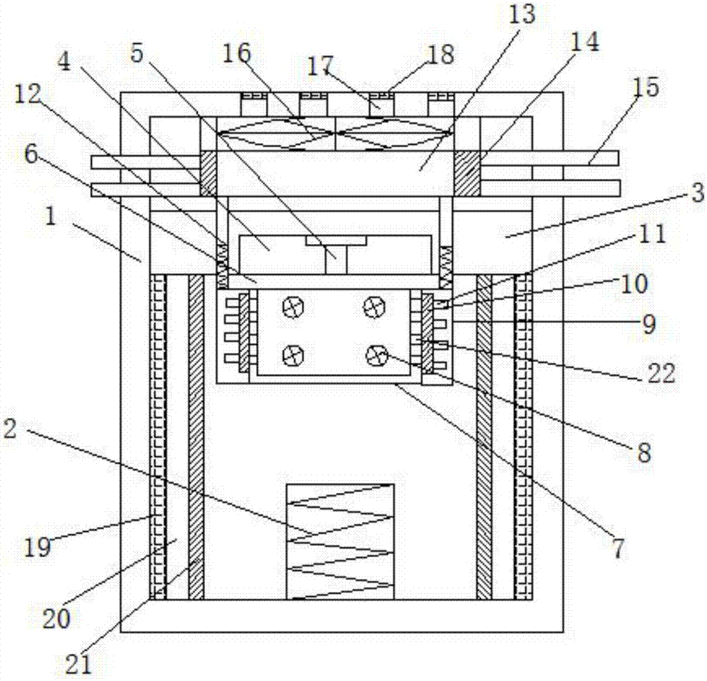
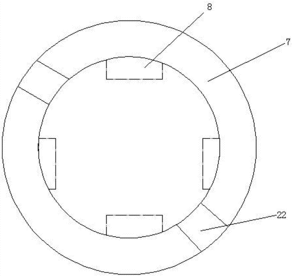
[0020] refer to Figure 1-2 , an energy-saving power transformer, comprising a frame 1, a transformer body 2 is fixedly connected to the inner wall of the bottom of the frame 1, a fixing plate 3 fixedly connected to the side wall of the frame 1 is installed directly above the transformer body 2, and the bottom of the fixing plate 3 is opened along its length direction There is a strip-shaped groove 4, the bottom of the strip-shaped groove 4 is fixedly connected with a telescopic rod, one end of the telescopic rod is fixedly connected with a support plate 6, the bottom of the support plate 6 is vertically fixedly connected with a casing 7, and the inner wall of the cas...


PUM


Abstract

The invention discloses an energy-saving power transformer. The energy-saving power transformer includes a frame, the inner wall of the bottom of the frame is fixedly connected with a transformer body, a fixing plate fixedly connected with the side wall of the frame is installed above the transformer body, the bottom of the fixing plate is provided with a long-strip-shaped groove in the length direction, the bottom of the long-strip-shaped groove is fixedly connected with a telescopic rod, one end of the telescopic rod is fixedly connected with a support plate, the bottom of the support plateis vertically and fixedly connected with a cover shell, the inner wall of the cover shell is symmetrically provided with first motors, the outer wall of the cover shell is symmetrically and fixedly connected with connection boxes, the portions, close to the side wall of the outer wall of the cover shell, of the connection boxes are internally provided with heat absorption silica gel, one side of the heat absorption silica gel is fixedly connected with cooling fins, and the tops of the connection boxes are fixedly connected with telescopic tubes. The energy-saving power transformer is simple and convenient to design, the practicability of the transformer is greatly improved, operation is simple, the production cost is low, and the energy-saving power transformer is very economical and is suitable for large-scale popularization.

Description

technical field [0001] The invention relates to the technical field of transformers, in particular to an energy-saving power transformer. Background technique [0002] Transformer is a device that uses the principle of electromagnetic induction to change AC voltage. The main components are primary coil, secondary coil and iron core (magnetic core). The main functions are: voltage conversion, current conversion, impedance conversion, isolation, voltage stabilization (magnetic saturation transformer), etc. According to the use, it can be divided into: power transformers and special transformers (electric furnace transformers, rectifier transformers, power frequency test transformers, voltage regulators, mining transformers, audio transformers, intermediate frequency transformers, high frequency transformers, impact transformers, instrument transformers, electronic transformers , reactors, transformers, etc.). [0003] Because some transformers are installed in the corridors ...

Claims


Application Information

Patent Timeline
Patent Type & Authority Applications(China)
IPC IPC(8): H01F27/02H01F27/08H01F27/22H01F27/33
Inventor 赵正萍
Owner ANHUI BAIHUA ELECTRIC POWER TECH CO LTD
Why Eureka
Try Eureka