Top cap for lithium ion battery

A lithium-ion battery and top cover technology, applied in battery pack parts, circuits, electrical components, etc., can solve problems such as lithium-ion battery explosion, protection circuit failure, huge impact, etc., to reduce the probability of scrapping and prevent overcharging. Effect

Inactive Publication Date: 2018-01-12
苏州绿标新能源科技有限公司
View PDF3 Cites 5 Cited by
  • Summary
  • Abstract
  • Description
  • Claims
  • Application Information

AI Technical Summary

Problems solved by technology

[0003] Lithium-ion power batteries used in electric vehicles or energy storage power stations generally use aluminum shell or steel shell square batteries. This kind of battery structure is stable, reliable, light, and has high energy density. Multiple square batteries are connected in series or in parallel to the protection circuit board to ensure the normal charging and discharging of lithium-ion batteries. However, since lithium-ion power batteries are generally used in automobiles, they are susceptible to large vibrations during use, and even huge Shock, the use environment is very complicated, it is easy to cause the protection circuit to fail
Once the protection circuit fails, when the lithium-ion battery is charged, overcharging is prone to occur, causing the electrolyte in the lithium-ion battery to decompose, and gas is generated inside the lithium-ion battery. Once the gas accumulates too much, the internal pressure of the battery is too high , it is easy to cause the explosion of the lithium-ion battery. Since the shell of the lithium-ion power battery is generally an aluminum shell or a steel shell structure, once an explosion occurs, it will cause great damage to the surrounding environment.

Method used


Image

  • Top cap for lithium ion battery
  • Top cap for lithium ion battery
  • Top cap for lithium ion battery

Examples


Embodiment Construction

[0024] In order to make the purpose of the invention, technical solution and beneficial technical effects of the present invention clearer, the present invention will be further described in detail below in conjunction with the accompanying drawings and specific implementation methods. It should be understood that the specific implementations described in this specification are only for explaining the present invention, not for limiting the present invention.

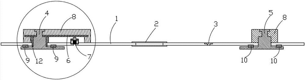
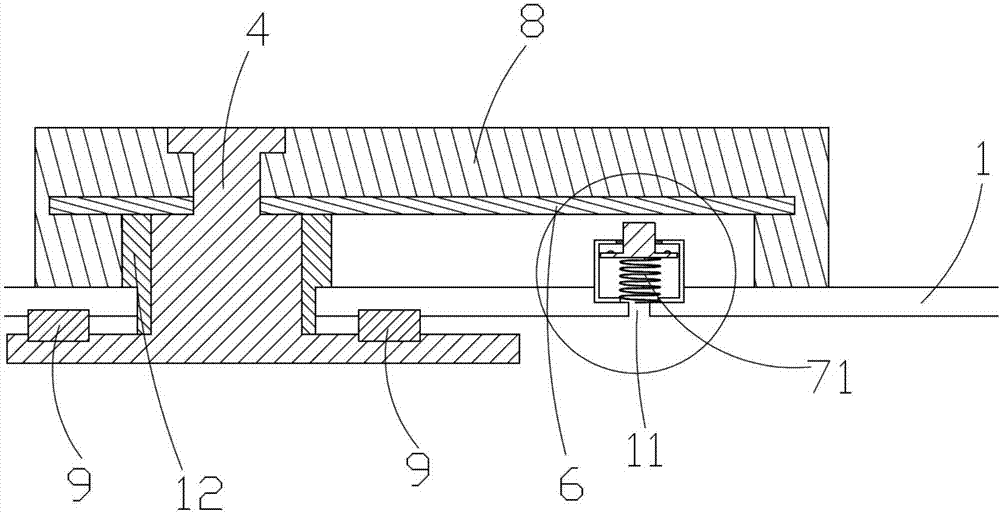
[0025] Such as Figure 1-2 As shown, a top cover for a lithium ion battery includes a top cover cover plate 1, a liquid injection hole 3 arranged on the top cover cover plate 1, an explosion-proof hole 2, and a cover through the top cover cover respectively. plate 1 and fixed on the first electrode pole 5 and the second electrode pole 4 on the top cover plate 1; wherein, the first electrode pole 5 is electrically connected with the top cover plate 1, and In this embodiment, the upper part of the first electrode pole 5 ...


PUM


Abstract

The invention discloses a top cap for a lithium ion battery. The top cap comprises a top cap cover plate, an electrolyte injecting hole, an explosion-proof hole, a first electrode pole and a second electrode pole, wherein the electrolyte injecting hole and the explosion-proof hole are formed in the top cap cover plate; the first electrode pole and the second electrode pole respectively penetrate through the top cap cover plate and are fixed on the top cap cover plate; the first electrode pole is conductively connected with the top cap cover plate; the second electrode pole is in insulated connection with the top cap cover plate; in addition, an electric connecting sheet which is conductively connected with the second electrode pole is arranged on the second electrode pole; a voltage measuring hole is also formed in the top cap cover plate; an overcharge preventing device is arranged above the voltage measuring hole, is electrically connected with the top cap cover plate and is locatedbelow the electric connecting sheet; when the internal air pressure inside the battery is greater than or equal to a preset value, the overcharge preventing device is electrically connected with the electrical connecting sheet; when the air pressure inside the battery is smaller than the preset value, the overcharge preventing device is in insulated assembly with the electrical connecting sheet.

Description

technical field [0001] The invention belongs to the field of lithium ion batteries, in particular to a top cover for lithium ion batteries. Background technique [0002] With the development of the global economy, especially the development of the automobile industry, people consume more and more traditional energy, and the contradiction between energy supply and demand continues to escalate. People are eager to develop new clean energy to replace traditional energy to meet people's daily needs. The needs of life, while reducing environmental pollution. Driven by this demand, lithium-ion power batteries came into being. [0003] Lithium-ion power batteries used in electric vehicles or energy storage power stations generally use aluminum shell or steel shell square batteries. This kind of battery structure is stable, reliable, light, and has high energy density. Multiple square batteries are connected in series or in parallel to the protection circuit board to ensure the no...

Claims


Application Information

Patent Timeline
Patent Type & Authority Applications(China)
IPC IPC(8): H01M2/04H01M2/10H01M2/34H01M50/147H01M50/578
CPCY02E60/10
Inventor 夏桂生
Owner 苏州绿标新能源科技有限公司
Why Eureka
Try Eureka