Check patentability & draft patents in minutes with Patsnap Eureka AI!

Electronic system

A technology of electronic systems and components, applied in the direction of electrical components, circuit devices, battery circuit devices, etc., can solve problems such as loss and large energy

Active Publication Date: 2018-01-12
DR ING H C F PORSCHE AG
View PDF9 Cites 2 Cited by
  • Summary
  • Abstract
  • Description
  • Claims
  • Application Information

AI Technical Summary

Problems solved by technology

[0004] The production costs of known multilevel inverters are especially due to the large number of switching elements
Furthermore, the relatively large number of switching elements also causes relatively large energy losses

Method used


Image

  • Electronic system
  • Electronic system
  • Electronic system

Examples


Embodiment Construction

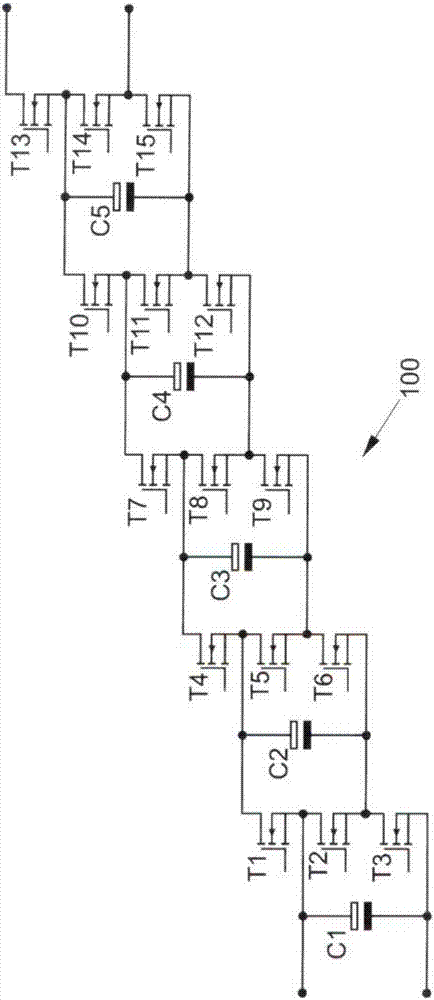
[0040] exist figure 1 The electronic system 100 shown in FIG. 2 includes a plurality of switching elements T1 to T15 and a plurality of energy storage elements C1 to C5. In the electronic system 100, the switching elements T1 to T15 are designed as semiconductor switches in the form of transistors. These switching elements T1 to T15 are switchable into a conductive state and a non-conductive state. Only which switching elements are switched into a conductive state will be described below. Switching elements not mentioned are switched into a non-conductive state.

[0041] Furthermore, the electronic system 100 comprises two input terminals connected to the energy storage element C1 and two output terminals, one output terminal connected to the switching element T13 and one output terminal connected to the two switching elements T14 and T15 . However, it is also possible to connect the electronic system 100 in reverse order, so that one of the input terminals is connected to...


PUM


Abstract

An electronic system includes a plurality of switching elements (T) and a plurality of energy storage elements (L; C). The energy storage elements (L; C) are connected to one another by the switchingelements (T). The energy storage elements (L; C) can be selectively switched to a first, a second or a third state by switching the switching elements (T). In the first state, the energy storage elements (L; C) are connected in series with one another. In the second state, the energy storage elements (L; C) are connected in parallel with one another. In the third state, the energy storage elements(L; C) are bypassed, wherein two of the energy storage elements (L; C) are each connected by no more than three of the switching elements (T).

Description

technical field [0001] The invention relates to an electronic system having a plurality of switching elements and a plurality of energy storage elements. Background technique [0002] An inverter is used in order to generate a current with a periodically varying voltage amplitude from the direct current output by the energy storage element. In inverters from the prior art, semiconductor elements are used as switching elements with particularly short switching frequencies. [0003] Furthermore, a technology also known as a multilevel inverter or multilevel inverter is known from the prior art, in which during the operation of the inverter individual modules each with an energy storage element It is possible to switch between different states dynamically. These modules can be connected in series with each other or in parallel with each other. It is also possible to bridge the modules. The output voltage of the inverter is thus generated by the dynamically implemented serie...

Claims


Application Information

Patent Timeline
Patent Type & Authority Applications(China)
IPC IPC(8): H02M7/483
CPCH02M7/483H02M7/4835H02M1/0095H02J1/10H02M7/48H02J2207/20H02M3/06H02M1/08
Inventor S·戈茨
Owner DR ING H C F PORSCHE AG
Features
  • R&D
  • Intellectual Property
  • Life Sciences
  • Materials
  • Tech Scout
  • Unparalleled Data Quality
  • Higher Quality Content
  • 60% Fewer Hallucinations
Learn More