
Method for making orthodontic micro-implant implanting guide plate

A technology of micro-implantation and micro-implantation nails, which is applied in the field of orthodontics, can solve problems such as micro-implantation failures, and achieve the effect of improving accuracy and stability

Inactive Publication Date: 2018-01-16
STOMATOLOGY AFFILIATED STOMATOLOGY HOSPITAL OF GUANGZHOU MEDICAL UNIV
View PDF3 Cites 11 Cited by
  • Summary
  • Abstract
  • Description
  • Claims
  • Application Information

AI Technical Summary

Problems solved by technology

Traditionally, the implantation position and direction of micro-implants are judged by the experience of doctors. Different doctors have different experience and proficiency in operation. It is likely that the micro-implants will fail due to the deviation of implantation position or direction.
Moreover, the traditional design of the implantation position of the micro-implant cannot realize the design of multiple implantation positions at one time.

Method used


Image

  • Method for making orthodontic micro-implant implanting guide plate
  • Method for making orthodontic micro-implant implanting guide plate

Examples


Embodiment 1

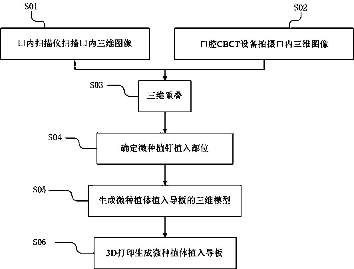
[0025] Such as figure 1 As shown, a method for making a micro-implant for orthodontic implantation includes the following steps:

[0026] S001: Use the 3 shape Trios scanner (a kind of color intraoral scanner) to obtain the patient's intraoral data, extend the scanning head into the patient's mouth, and scan uniformly along the surface of the patient's dental crown, which can quickly obtain the true situation of the patient's mouth. Clearly and accurately distinguish the color of gums and teeth;

[0027] S002: Use CBCT (cone beam projection computer reconstruction tomography equipment) to scan the maxillofacial region. When shooting, the subject sits relaxed, the orbital ear plane is parallel to the ground plane, the midline of the plane (mid-sagittal plane) is perpendicular to the ground plane, and the cusps are kept in a staggered bite. Use NNTViewer software (an image analysis software) to convert CBCT images into medical digital image communication standard storage;

[0028] S0...

Embodiment 2

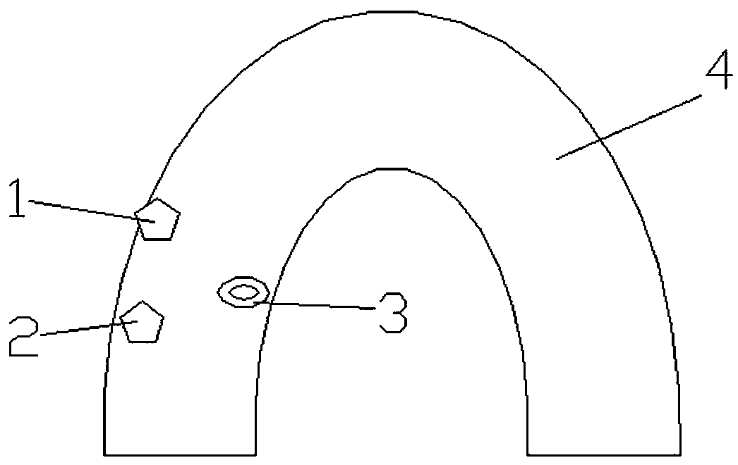
[0036] Such as figure 1 , 2 As shown, the lingual implantation of micro-implants for the upper and lower first molars and second molars is taken as an example. A method for making 3 orthodontic micro-implant implant guides includes the following steps:

[0037] S0001: The patient's intraoral data obtained by the 3 shape Trios scanner, extend the scanning head into the patient's oral cavity, and scan uniformly along the surface of the patient's dental crown, which can quickly obtain the true situation of the patient's oral cavity;

[0038] S0002: Scan the maxillofacial area with a CBCT machine. When shooting, the subject sits relaxed, the orbital ear plane is parallel to the ground plane, the midline of the face (mid-sagittal plane) is perpendicular to the ground plane, and the cusp bite is maintained , Convert CBCT images into medical digital image communication standard storage with NNTViewer software;

[0039] S0003: Use MIMICS 15.0 software to perform 3D reconstruction of scann...


PUM


Abstract

The invention relates to the technical field of dental orthodontics, and more specifically, relates to a method for making an orthodontic micro-implant implanting guide plate. The method includes thefollowing steps: S01, scanning an intraoral three-dimensional (3D) image of a patient with an intraoral scanner; S02, shooting a maxillofacial 3D image of the patient with an oral CBCT device; S03, overlapping the 3D images and data obtained in the former two steps; S04, according to the overlapped image and data, designing a micro-implant nail implant position or implant port diameter size, and generating data; S05, introducing the images and data in the step S03 and S04 into a micro-implant implanting guide plate system, and generating a 3D model of the micro-implant implanting guide plate;and S06, introducing the 3D model of the micro-implant implanting guide plate into a 3D printer, and generating the micro-implant implanting guide plate via 3D printing, wherein the generated micro-implant implanting guide plate can be used for designing more reasonable micro-implant nail implanting position.

Description

Technical field [0001] The present invention relates to the technical field of orthodontics, and more specifically, to a method for manufacturing a micro-implant implant guide plate for orthodontics. Background technique [0002] In the process of orthodontic treatment, it is often necessary to implant micro-implants to assist tooth movement. The implantation site of the microimplant not only needs to avoid the roots, important blood vessels / nerves and other anatomical structures, but also requires the implantation site to be located on the attached gums to obtain good stability. Traditionally, the placement and direction of the micro-implant are judged by the doctor’s experience. Different doctors have different experience and operating proficiency. It is likely that the deviation of the placement or direction will lead to the failure of the micro-implant. . Moreover, the traditional design of the implantation position of the micro-implant cannot realize the design of multiple...

Claims


Application Information

Patent Timeline
IPC IPC(8): A61C7/00B33Y80/00
Inventor 陈良娇王朝俭
Owner STOMATOLOGY AFFILIATED STOMATOLOGY HOSPITAL OF GUANGZHOU MEDICAL UNIV
Learn More