
Film tearing mechanism of film sticking machine and film tearing method thereof

A technology of film laminating machine and jacking mechanism, which is applied in the direction of unsealing, packaging, transportation and packaging of objects, which can solve the problems of non-reusable waste of tape, failure of roller tearing film, and easily damaged products, so as to reduce labor intensity, The effect of reducing consumables and lowering the cost of use

Inactive Publication Date: 2018-01-16
苏州威创达智能设备有限公司
View PDF8 Cites 6 Cited by
  • Summary
  • Abstract
  • Description
  • Claims
  • Application Information

AI Technical Summary

Problems solved by technology

The former method is wasteful due to the use of adhesive tape, which cannot be used repeatedly, and the structure is too complicated and the cost is too high; the latter method will fail to tear the film due to the decrease in the viscosity of the roller over time, so it needs to be replaced frequently, and the cost is too high. High, when the roller is pressed against the surface of the product, it is easy to damage the product
In addition, the first two methods, because the product completely depends on the vacuum adsorption of the jig when tearing the film, may easily cause the product to shift during the film tearing process and the accuracy will drop

Method used


Image

  • Film tearing mechanism of film sticking machine and film tearing method thereof
  • Film tearing mechanism of film sticking machine and film tearing method thereof
  • Film tearing mechanism of film sticking machine and film tearing method thereof

Examples


Embodiment Construction

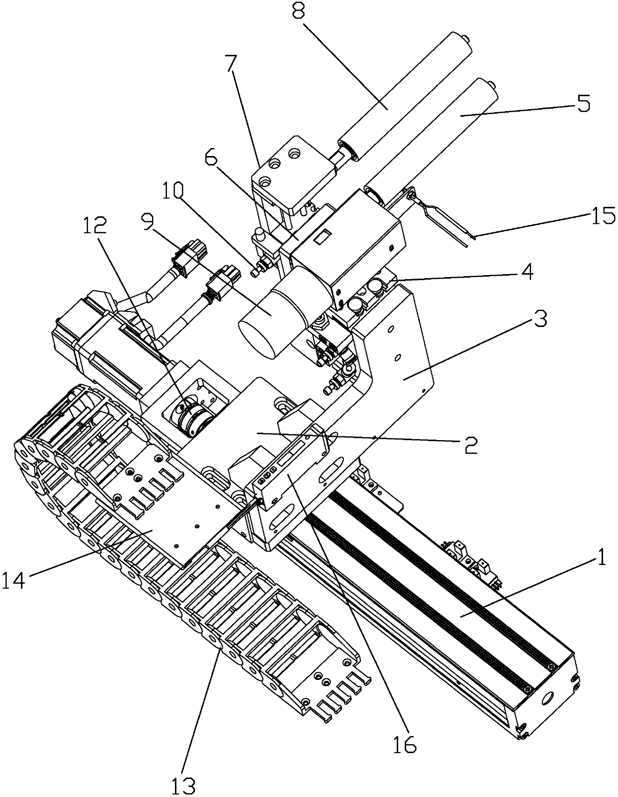
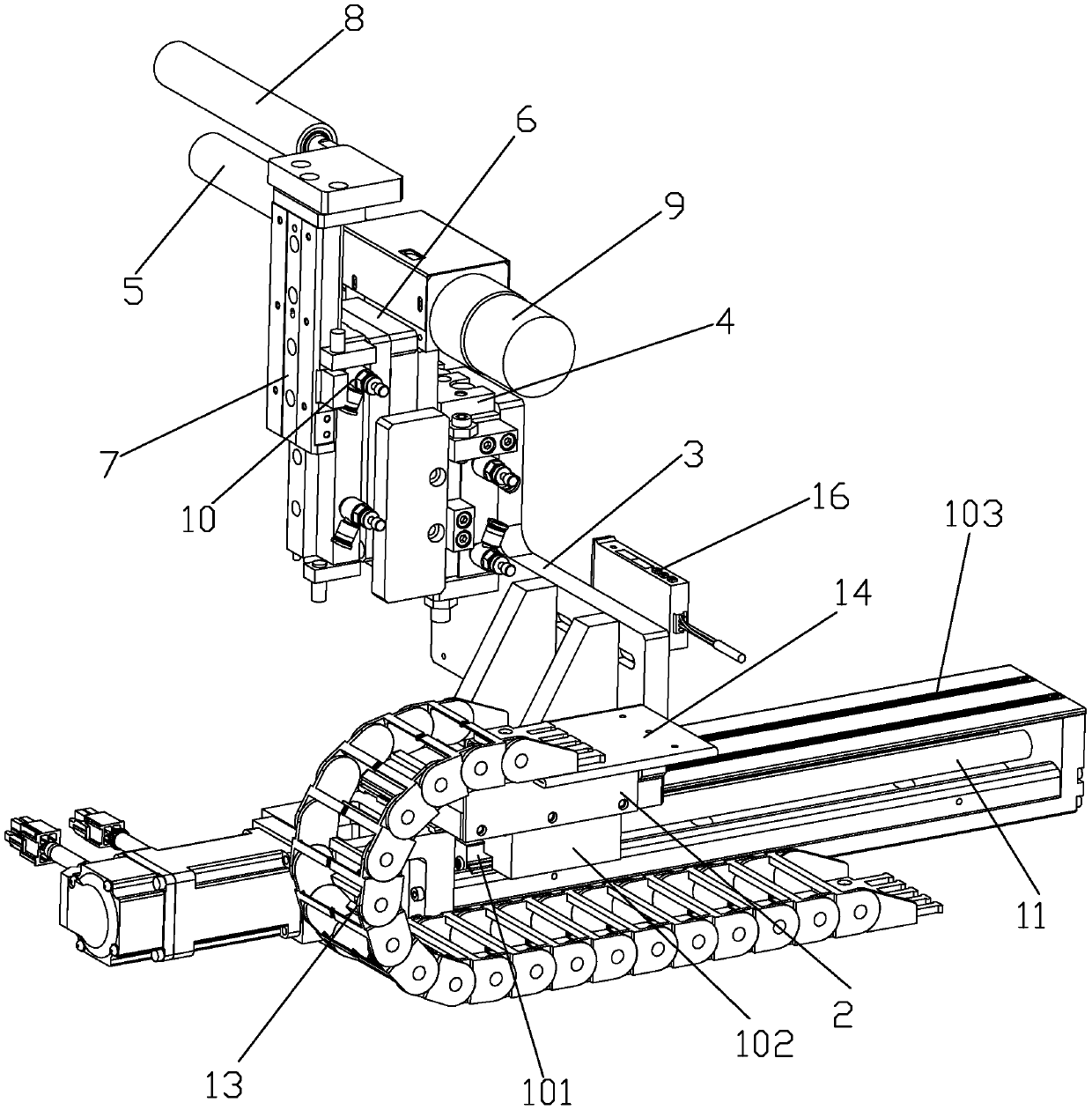
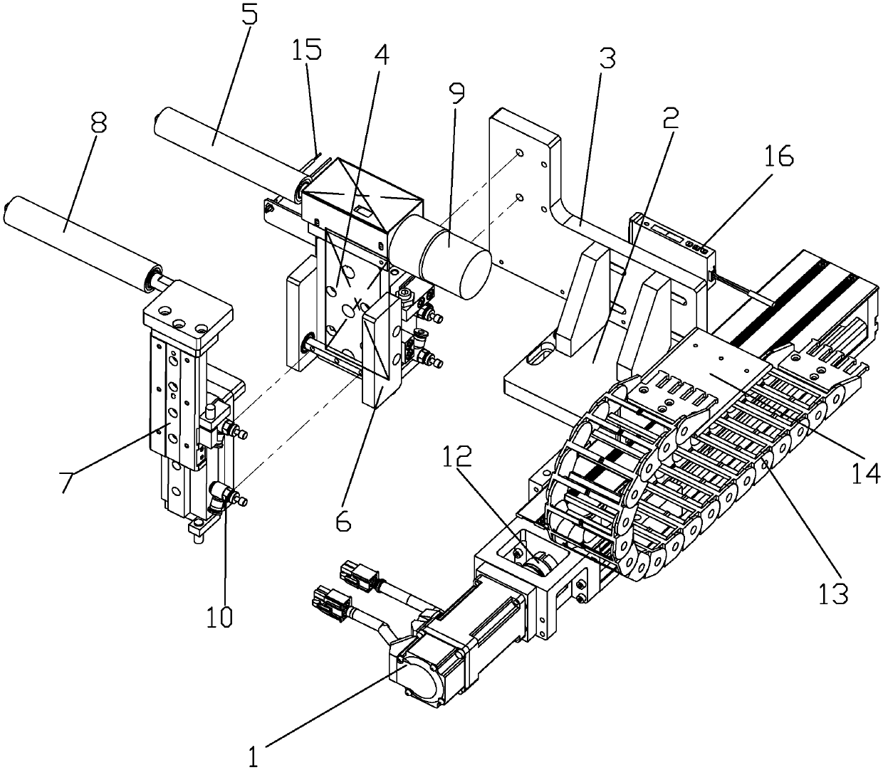
[0031] A film tearing mechanism of a film laminating machine provided in this embodiment has a structure such as Figure 1-4 shown.

[0032] The film tearing mechanism includes a jacking mechanism, a clamping mechanism and a forward and backward mechanism.

[0033] The forward and backward mechanism includes a linear motor 1 , a forward and backward base 2 , a main mounting plate 3 , a guide shaft 11 and a coupling 12 . The linear motor 1 includes a mover 101, a mover base 102, an upper cover 103, and a fixed shaft. The forward and backward base 2 is fixed to the mover base 102 and is located above the upper cover 103. The main mounting plate 3 is fixed on the forward and backward base 2. And protruding to one side in a cantilever shape, the fixed shaft and the guide shaft 11 are coaxially connected through the coupling 12 , and are installed on the central axis of the mover 101 and parallel to the moving direction of the linear motor 1 . The linear motor 1 also includes a s...


PUM


Abstract

The invention discloses a film tearing mechanism of a film sticking machine, and relates to the field of electronic product machining. The film tearing mechanism comprises a jacking mechanism, a clamping mechanism and an advance and backstep mechansim, wherein the advance and backstep mechansim comprises a linear motor, an advance and backstep base and a main installation board, the linear motor comprises a mover base and an upper cover, the advance and backstep base is fixed to the mover base and located above the upper cover, the main installation board is fixed to the advance and backstep base and extends out of one side of the advance and backstep base to form a cantilever, the jacking mechanism comprises a jacking air cylinder, a jacking roller and an auxiliary installation board, thejacking air cylinder is vertically fixed to the main installation board, the auxiliary installation board is fixed to one side of the jacking air cylinder, the jacking roller is fixed to the top of the auxiliary installation board, the clamping mechanism comprises a clamping air cylinder and a clamping roller, the clamping air cylinder is vertically fixed to the auxiliary installation board, theclamping roller is fixed to the top of the clamping air cylinder and located above the jacking roller, a product with a film to be torn can be contained between the jacking roller and the clamping roller and the surface of the product sticking to the film faces downward. According to the film tearing mechanism, the precision is high, consumables are few, the cost is low, and the product is not likely to be damaged.

Description

technical field [0001] The invention relates to the technical field of electronic product processing, in particular to a film tearing mechanism of a film laminating machine and a film tearing method thereof. Background technique [0002] There is usually a layer of film material attached to the surface of electronic products, and artificial tearing of the film will leave traces such as fingerprints on the surface of the product. The film tearing mechanism in the prior art includes a manipulator with a film tearing module to tear the film, and the film tearing module uses adhesive tape to tear the film, and another method uses sticky rollers to tear the film. The former method is wasteful due to the use of adhesive tape, which cannot be used repeatedly, and the structure is too complicated and the cost is too high; the latter method will fail to tear the film due to the decrease in the viscosity of the roller over time, so it needs to be replaced frequently, and the cost is t...

Claims


Application Information

Patent Timeline
Patent Type & Authority Applications(China)
IPC IPC(8): B65B69/00
Inventor 刘晨阳葛云石谭吉祥
Owner 苏州威创达智能设备有限公司
Learn More