A loading and unloading device capable of changing the direction of the cutter head

A loading and unloading device and cutter head technology, which is applied to storage devices, loading/unloading, and unstacking of objects, etc., can solve the problems of affecting loading and unloading efficiency, single use performance, and long transmission time, so as to improve the efficiency and cost of loading and unloading of objects. Low, the effect of improving the quality of use

Active Publication Date: 2022-05-13
NORTH CHINA UNIVERSITY OF SCIENCE AND TECHNOLOGY
View PDF0 Cites 0 Cited by
  • Summary
  • Abstract
  • Description
  • Claims
  • Application Information

AI Technical Summary

Problems solved by technology

[0003] The existing loading and unloading equipment usually has a simple structure and a relatively single performance. Usually, it can only change direction in one direction. In the actual use process, at least two driving mechanisms are required, which not only increases the cost, but also takes a long time to drive, affecting Loading and unloading efficiency, in addition, the cutter head for loading and unloading items is only convenient for clamping and fixing items of a specific size, which is less flexible and has great limitations in use. Therefore, we propose a loading and unloading tool that can change the direction of the cutter head The device is used to solve the above problems

Method used


Image

  • A loading and unloading device capable of changing the direction of the cutter head
  • A loading and unloading device capable of changing the direction of the cutter head
  • A loading and unloading device capable of changing the direction of the cutter head

Examples


Embodiment

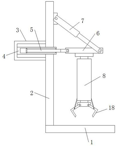
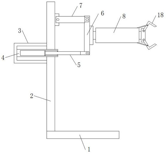
[0026] refer to Figure 1-4 , a loading and unloading device that can change the direction of the cutter head, including a fixed seat 1 and a support plate 2, the support plate 2 is vertically installed on the top side of the fixed seat 1, and also includes a steering mechanism and a loading and unloading mechanism at the bottom of the steering mechanism;

[0027] Wherein the steering mechanism installed on the support plate 2 includes a fixed bracket 3 and a hydraulic cylinder 7, the fixed bracket 3 is welded on the side of the support plate 2 away from the fixed seat 1, and the fixed bracket 3 is welded with a horizontally arranged fixed plate 4, the fixed plate One side of 4 is movably installed with a telescopic plate 5 located on the same level as the fixed plate 4, and one end of the telescopic plate 5 is rotatably connected to one end of a steering plate 6, and the steering plate 6 is located directly above the fixed seat 1, and the hydraulic cylinder 7 rotates Installe...


PUM


Abstract

The invention discloses a loading and unloading device capable of changing the direction of the cutter head, which comprises a fixing base and a supporting plate, the supporting plate is vertically installed on the top side of the fixing base, and also includes a steering mechanism and a loading and unloading mechanism at the bottom of the steering mechanism, wherein it is installed on the The steering mechanism on the support plate includes a fixed bracket and a hydraulic cylinder. The fixed bracket is welded on the side of the support plate away from the fixed seat. A horizontal fixed plate is welded in the fixed bracket. The expansion plate on the same horizontal plane, one end of the expansion plate is rotatably connected to one end of the steering plate, and the steering plate is located directly above the fixed seat, the hydraulic cylinder is rotatably installed on the side of the support plate close to the fixed seat, and the piston rod of the hydraulic cylinder is connected to the fixed seat. The other end of the steering plate is connected in rotation. The invention is reasonable in design, simple in operation, convenient and quick to change the loading and unloading direction of articles, and can clamp and fix articles of different specifications and sizes, thereby reducing costs and improving the loading and unloading efficiency of articles.

Description

technical field [0001] The invention relates to the technical field of article loading and unloading, in particular to a loading and unloading device capable of changing the direction of a cutter head. Background technique [0002] The basic actions of loading and unloading activities include loading (ships), unloading (ships), stacking, warehousing, warehousing, and short-distance transportation that connects the above actions, which are necessary activities associated with transportation and storage. In the process of logistics, loading and unloading activities are constantly appearing and repeated, and its frequency is higher than other logistics activities. Each loading and unloading activity takes a long time, so it often becomes the key to determining the logistics speed. In addition, loading and unloading Activities consume a lot of manpower. [0003] The existing loading and unloading equipment usually has a simple structure and a relatively single performance. Usua...

Claims


Application Information

Patent Timeline
Patent Type & Authority Patents(China)
IPC IPC(8): B65G47/90B65G67/02B65G67/60B65G61/00B65G1/04
Inventor 琚立颖王鑫阁裴未迟纪宏超龙海洋
Owner NORTH CHINA UNIVERSITY OF SCIENCE AND TECHNOLOGY
Why Eureka
Try Eureka