
Pipe robot three-axis differential mechanism

A pipeline robot and differential mechanism technology, applied in the direction of differential transmission, pipe components, special pipes, etc., can solve the problems of decreased effective traction force, low effective driving force, high manufacturing cost, etc., and achieve real-time performance, flexibility, and improved The effect of adaptability and improving the ability to overcome obstacles

Inactive Publication Date: 2020-02-07
CHONGQING UNIV OF TECH
View PDF5 Cites 0 Cited by
  • Summary
  • Abstract
  • Description
  • Claims
  • Application Information

AI Technical Summary

Problems solved by technology

Its disadvantages are that the structure and control method are complex and costly. When encountering irregular pipe walls or turning, the speed adjustment of the driving wheel is not real-time and lacks flexibility, resulting in increased power consumption, decreased effective traction, and poor obstacle-crossing ability. , increased wear of the driving device, etc., and because multiple motors will occupy a lot of space, such a robot is not suitable for use in small and medium-sized pipes
There are also very few pipeline robots that use gear differentials to solve some problems, but they fail to achieve three-axis differential adjustment, and each gear differential needs to use four bevel gears, resulting in large volume and poor structure. More complex, high manufacturing cost, it still has the problems of low effective driving force and poor obstacle-crossing ability

Method used


Image

  • Pipe robot three-axis differential mechanism
  • Pipe robot three-axis differential mechanism
  • Pipe robot three-axis differential mechanism

Examples


Embodiment Construction

[0027] The specific implementation manners of the present invention will be further described in detail below in conjunction with the accompanying drawings.

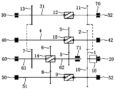
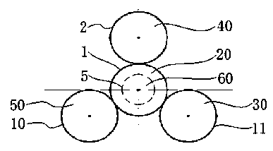
[0028] see figure 1 , the three-axis differential mechanism of the pipeline robot in a specific embodiment of the present invention includes an input shaft 20, one end of the input shaft 20 is fixedly installed with an input shaft gear 1, the other end of the input shaft 20 is rotationally connected with the housing 70, and the input shaft 20 is driven by a motor 16 located between the input shaft gear 1 and the housing 70 and fixedly coupled with the housing 70; it also includes a first rotating shaft 30, a second rotating shaft 40, a third rotating shaft 50, and a main differential shaft 60;

[0029] The first rotating shaft 30 includes a first front differential shaft 31 and a first rear differential shaft 32 , and the first front differential shaft 31 and the first rear differential shaft 32 are coupled through the f...


PUM


Abstract

The invention relates to a pipe-robot triaxial differential mechanism. The pipe-robot triaxial differential mechanism comprises an input shaft, and an input shaft gear is fixedly installed on the shaft; the pipe-robot triaxial differential mechanism also comprises a first rotating shaft, a second rotating shaft, a third rotating shaft and a main differential shaft, the four shafts comprise front differential shafts and back differential shafts, and the front differential shafts and the back differential shafts are connected through dual-worm differential mechanisms; transmission gears are fixedly installed on the first back differential shaft, the second back differential shaft and the third back differential shaft, and are engaged with the input shaft gear respectively, and the transmission ratio is 1:1; a fourth front linkage gear fixedly installed on the fourth front differential shaft is engaged with a first linkage gear fixedly installed on the first front differential shaft, andthe transmission ratio is 1:1; a fourth back linkage gear fixedly installed on the fourth back differential shaft is engaged with a second linkage gear fixedly installed on the second dual-worm differential mechanism, and the transmission ratio is 2:1; a fourth linkage gear fixedly installed on the fourth dual-worm differential mechanism is engaged with the third linkage gear fixedly installed onthe third front differential shaft, and the transmission ratio is 1:2. According to the pipe-robot triaxial differential mechanism, all wheel speeds can be differentially adjusted, the good obstacle crossing and turning capacities are achieved, the driving efficiency is high, the area is small, and the manufacturing cost is low.

Description

technical field [0001] The invention belongs to the technical field of general measures for generating and maintaining effective operation of machines or equipment in mechanical engineering, and in particular relates to a three-axis differential mechanism of a pipeline robot. Background technique [0002] As an important material transportation device, pipelines are widely used in water supply, drainage, heat supply, gas supply, long-distance transportation of oil and natural gas, agricultural irrigation, water conservancy projects and other fields. However, due to the defects of the pipeline itself or the effects of vibration, thermal cycle, corrosion, etc. during use, the pipeline will leak or be damaged. In order to prolong the service life of the pipeline and prevent accidents such as leakage, it is necessary to carry out effective inspection and maintenance on the pipeline on a regular basis , because most of the pipelines are underground, the internal environment of th...

Claims


Application Information

Patent Timeline
Patent Type & Authority Patents(China)
IPC IPC(8): F16H48/05F16L55/32F16L101/10F16L101/30
Inventor 蒋强郑超尹风
Owner CHONGQING UNIV OF TECH
Learn More