
A power distribution cabinet with good heat dissipation effect

A heat dissipation effect, power distribution cabinet technology, applied in substation/power distribution device shell, substation/switchgear cooling/ventilation, etc., can solve problems affecting the normal operation of the transmission system, aging of internal electrical components, poor heat dissipation, etc. Achieve good cooling effect, rapid cooling and good heat dissipation effect

Pending Publication Date: 2018-01-16
YINGTAI GROUP
View PDF0 Cites 6 Cited by
  • Summary
  • Abstract
  • Description
  • Claims
  • Application Information

AI Technical Summary

Problems solved by technology

[0002] The power distribution cabinet is a commonly used electrical equipment, which plays an irreplaceable role in the power transmission system. The power distribution cabinet will generate a lot of heat during the working process. If the heat is not dissipated in time, it will easily cause the aging of the internal electrical components if the heat is not dissipated in time.
In the prior art, the heat dissipation of the power distribution cabinet is mostly through the air, and the heat dissipation effect is poor, which not only causes damage to the equipment, but also affects the normal operation of the conveying system

Method used


Image

  • A power distribution cabinet with good heat dissipation effect
  • A power distribution cabinet with good heat dissipation effect
  • A power distribution cabinet with good heat dissipation effect

Examples


Embodiment Construction

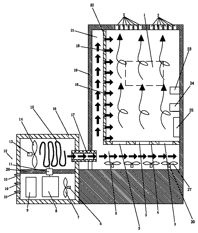
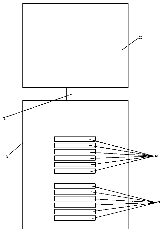
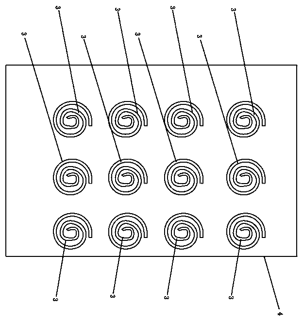
[0013] Such as Figure 1-3 As shown, a power distribution cabinet with good heat dissipation effect includes a cabinet body 19, a controller 1 arranged in the cabinet body 19, a temperature control system electrically connected to the controller 1, and a In the body 19, a humidity control system electrically connected to the controller 1; the temperature control system includes a temperature sensor 23 arranged on the inner wall of one side of the cabinet body 19, and also includes a set close to the cabinet body 19 and is connected to the cabinet body 19. The refrigerating box 12 connected to each other also includes a heat dissipation assembly arranged at the bottom of the inner wall of the cabinet body 19; 1. The lower end of the partition 26 is a heat dissipation part; the cooling part includes a cabinet 16 arranged at the lower end of one side of the cabinet 19 and connected with the cabinet 19, and also includes an evaporator installed in the cabinet 16 for refrigeration....


PUM


Abstract

The present invention discloses a power distribution cabinet with a good heat dissipation effect, pertaining to the technical field of power equipments. The power distribution cabinet comprises a cabinet body, a controller arranged in the cabinet body, a temperature control system electrically connected with the controller, and a humidity control system, wherein the humidity control system is arranged in the cabinet body and the humidity control system is electrically connected with the controller. The temperature control system comprises a temperature sensor arranged on the inner wall of oneside of the inside of the cabinet body; a refrigerating box, wherein the refrigerating box is arranged close to the cabinet body and the refrigerating box is connected with the cabinet body; and heatdissipation components arranged on the bottom of the inner wall of the cabinet body. The middle part of the refrigerating box is provided with a partition plate. A refrigerating part is located on theupper end of the partition plate, in the refrigerating box. A heat dissipation part is located under the lower end of the partition plate, in the refrigerating box. The refrigerating part comprises abox body, wherein the box body is arranged at the lower end of one side of the cabinet body and the box body is connected with the cabinet body; an evaporator, wherein the evaporator is arranged in the box body and the evaporator is used for refrigerating; a cold air fan used for inducing air; and a cold air motor used for driving the cold air fan. The power distribution cabinet can be used for refrigeration and dehumidification, and the power distribution cabinet has the advantages of convenience for using and good heat dissipation effect.

Description

technical field [0001] The invention relates to the technical field of power equipment, in particular to a power distribution cabinet with good heat dissipation effect. Background technique [0002] The power distribution cabinet is a commonly used electrical equipment, which plays an irreplaceable role in the power transmission system. The power distribution cabinet will generate a lot of heat during the working process. If the heat is not dissipated in time, it will easily cause the aging of the internal electrical components if the heat is not dissipated in time. . In the prior art, the heat dissipation of the power distribution cabinet is mostly through the air, and the heat dissipation effect is poor, which not only causes damage to the equipment, but also affects the normal operation of the conveying system. Contents of the invention [0003] The purpose of the present invention is to provide a power distribution cabinet with good heat dissipation effect, which can ...

Claims


Application Information

Patent Timeline
IPC IPC(8): H02B1/56H02B1/28H02B1/30
Inventor 王生红马一文
Owner YINGTAI GROUP
Learn More