Corrosion-resistant magnetic drive centrifugal pump

A magnetic drive, corrosion-resistant technology, used in pumps, pump devices, pump components, etc., can solve the problems of inability to stop at will, incompetence, and inexhaustible discharge of residual liquid, achieving good cooling and lubrication effects, reasonable design and structure, The effect of reducing volume loss

Inactive Publication Date: 2019-12-03
温州市邦明机械设备制造有限公司
View PDF8 Cites 2 Cited by
  • Summary
  • Abstract
  • Description
  • Claims
  • Application Information

AI Technical Summary

Problems solved by technology

When the magnetic pump transports the crystallization medium, it should be cleaned with clean water in time after use, and the residual liquid in the pump should be drained, which will cause environmental pollution
And there is a phenomenon that the residual liquid in the pump cannot be exhausted
When shutting down, the crystallization medium that has not been emptied solidifies, and when restarting, the resistance is large, which will cause damage to the bearing and even fail to start. This requires melting the solidified crystallization medium, and the crystallization medium at the inner magnetic rotor cannot be used. The heat source reaches this area, so that it cannot stop at will when transporting crystallization-prone media
[0003] However, for the highly corrosive and easily crystallized working conditions, such as transporting potassium nitrate solution, ordinary high-temperature multi-stage magnetic drive centrifugal pumps are generally not competent, and the general jacket cannot directly act on the outer shell of the fluid, while directly The thermal insulation effect of the connecting body of the driving part cannot guarantee the thermal insulation effect, and due to the temperature of the insulation, the life of the rolling bearing of the driving part may be affected when the connecting body is directly insulated.

Method used


Image

  • Corrosion-resistant magnetic drive centrifugal pump
  • Corrosion-resistant magnetic drive centrifugal pump
  • Corrosion-resistant magnetic drive centrifugal pump

Examples


Embodiment Construction

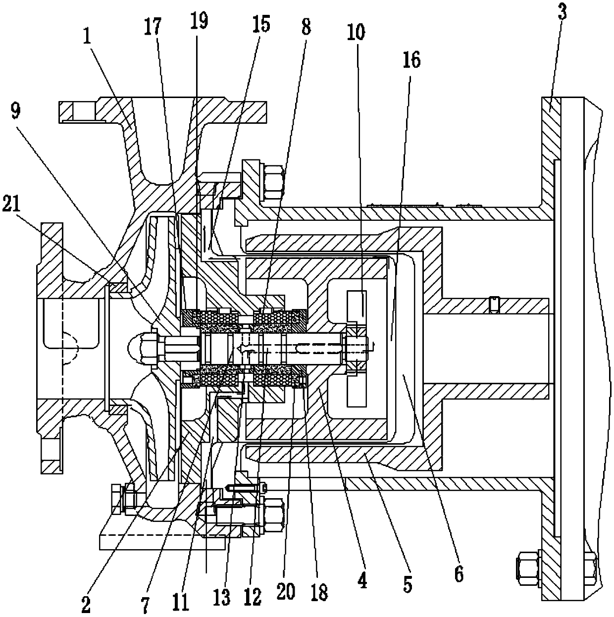
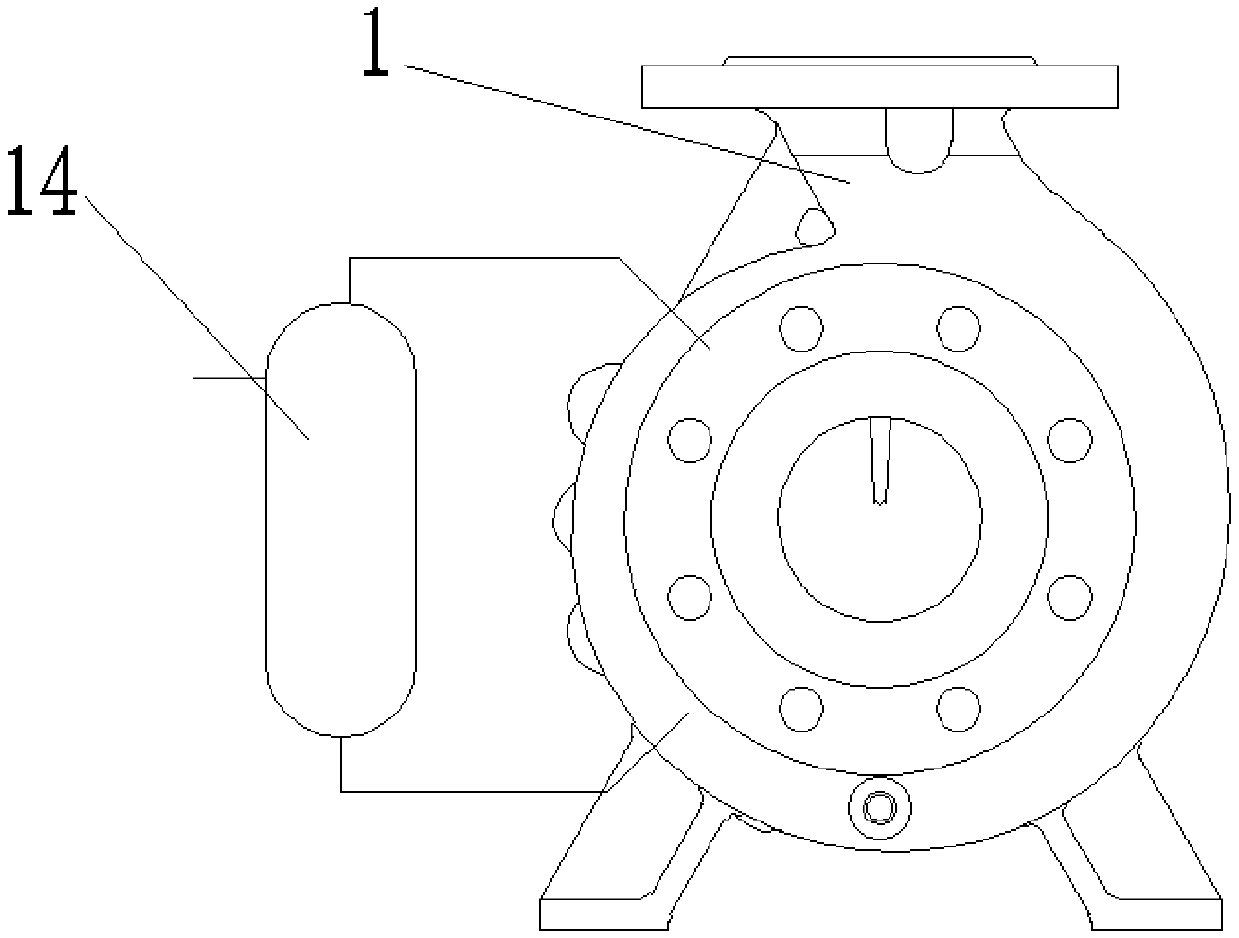
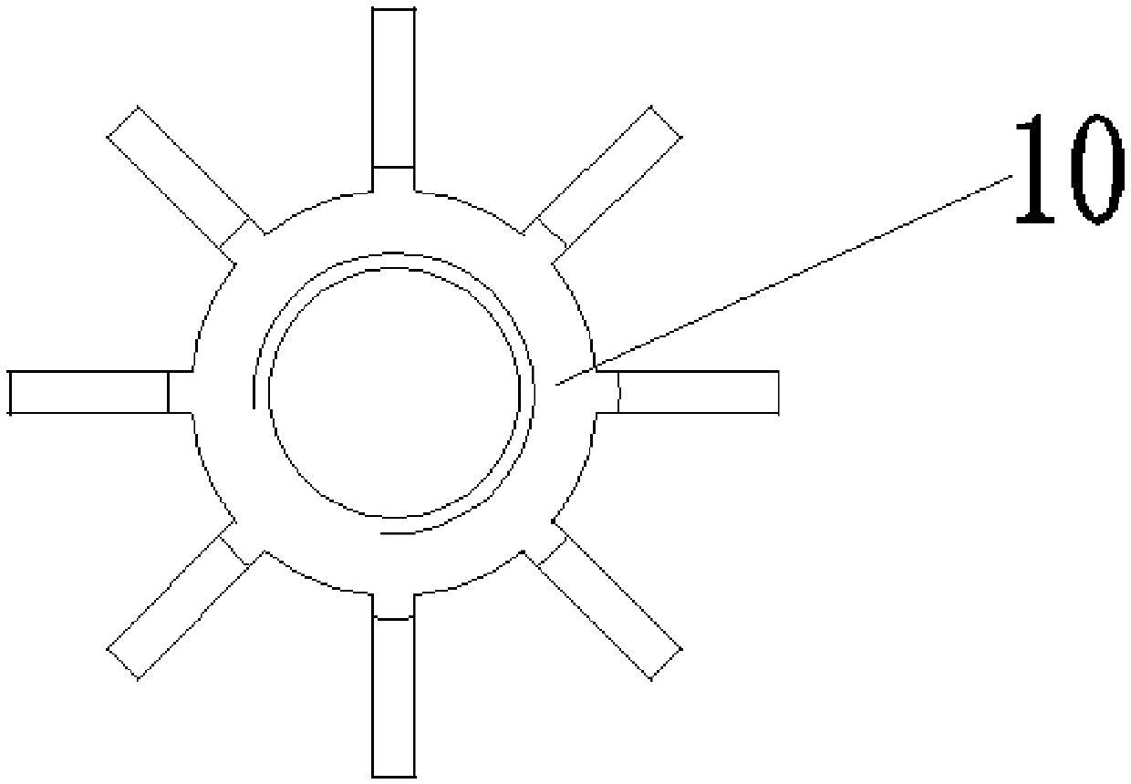
[0016] Such as Figure 1-Figure 3 As shown, a corrosion-resistant magnetic drive centrifugal pump includes a pump body 1, a pump cover 2, a suspension 3, an inner magnetic rotor 4 and an outer magnetic rotor 5, and the outer magnetic rotor 5 is fixed on the suspension 3. A spacer 6 is provided between the outer magnetic rotor 5 and the inner magnetic rotor 4, and the corrosion-resistant magnetic drive centrifugal pump also includes a drive delivery shaft 7, and the drive delivery shaft 7 is fixed on the pump cover 2 through two sliding bearings 8 , the front end of the drive delivery shaft 7 is fixed with an impeller 9, and the rear end of the drive delivery shaft 7 is provided with an agitator 10, the inner magnetic rotor 4 is arranged at the rear portion of the drive delivery shaft 7, and the agitator 10 is provided with In the middle of the inner magnetic rotor 4, the space between the inner magnetic rotor 4 and the isolation sleeve 6;

[0017] The pump cover 2 is provided...


PUM


Abstract

The invention discloses a corrosion-resistant magnetic drive centrifugal pump. A first conveying channel is arranged on a pump cover, and a second conveying channel is arranged on a driving conveyingshaft, is arranged on the central axis of the driving conveying shaft and extends towards the rear end to extend out of the driving conveying shaft along the central axis. A conveying opening is formed on the driving conveying shaft, one end of the first conveying channel is connected to a buffer liquid storage tank, and the other end is connected with a conveying port of the second conveying channel. A third conveying channel is further formed on the pump cover, the first conveying channel and the third conveying channel both extend inwards from the outer wall of the pump cover to penetrate through the pump cover, one end of the third conveying channel is connected to the buffer liquid storage tank, and the other end communicates with an annular gap area between an isolation sleeve and aninner magnetic rotor, so that the problem that heat preservation is needed during the conveying process is solved, the media which are easy to crystallize and high in corrosivity do not enter a driving cavity, the driving shaft is protected, and the service life is prolonged; the cooling and lubricating effects are good, the driving conveying shaft achieves a good driving effect, and the volume loss is well reduced.

Description

technical field [0001] The invention relates to a pump, in particular to a corrosion-resistant magnetic drive centrifugal pump. Background technique [0002] The magnetic pump consists of three parts: the pump, the magnetic driver and the motor. The pump includes the casing, the impeller, the pump cover and the pump shaft. The magnetic driver includes the outer magnetic rotor, the inner magnetic rotor and the isolation sleeve. The motor and the outer magnetic rotor are connected together. The driving part is formed. The impeller and the inner magnetic rotor are connected together to form the driven part. There is a sealed isolation sleeve between the inner magnetic rotor and the outer magnetic rotor. The inner magnetic rotor is in the medium, and the motor rotates through the magnetic poles of the outer magnetic rotor and the inner magnetic rotor. The push-pull resultant force composed of suction and repulsion generated by the magnetic pole coupling of the rotor drives the i...

Claims


Application Information

Patent Timeline
Patent Type & Authority Applications(China)
IPC IPC(8): F04D7/06F04D13/02F04D29/00F04D29/06F04D29/16F04D29/22F04D29/58B01F13/08
CPCF04D13/024F04D7/06F04D29/22F04D29/007F04D29/061F04D29/5886F04D29/167B01F33/453
Inventor 韩帮明
Owner 温州市邦明机械设备制造有限公司
Why Eureka
Try Eureka