
Decomposition method of solving discrete control-containing electric power system reactive optimization

A discrete control and power system technology, applied in reactive power compensation, AC network voltage adjustment, etc., can solve problems such as difficult to ensure algorithm convergence, time-consuming, and unfeasible optimization results

Active Publication Date: 2018-01-16
SOUTH CHINA UNIV OF TECH
View PDF3 Cites 10 Cited by
  • Summary
  • Abstract
  • Description
  • Claims
  • Application Information

AI Technical Summary

Problems solved by technology

Although the penalty function method has high solution efficiency, the selection of the penalty factor and the timing of its introduction in the iterative process have a great impact on the algorithm, and it needs to be adjusted according to the specific situation.
The branch and bound method is applied to solve the large-scale reactive power optimization problem with discrete control, which takes a long time, and even cannot obtain the optimization result in a limited time
When the sensitivity method uses the sensitivity information to convert the MINLP model to the MILP model, a certain approximation is made to the model, the solution accuracy will be reduced, and it may even cause the optimization result to be infeasible after the discrete variable values ​​are fixed.
Although the Benders decomposition method can decompose the MINLP model, it is difficult to guarantee the convergence of the algorithm in theory because the method requires the original problem to be a convex model.

Method used


Image

  • Decomposition method of solving discrete control-containing electric power system reactive optimization
  • Decomposition method of solving discrete control-containing electric power system reactive optimization
  • Decomposition method of solving discrete control-containing electric power system reactive optimization

Examples


Embodiment

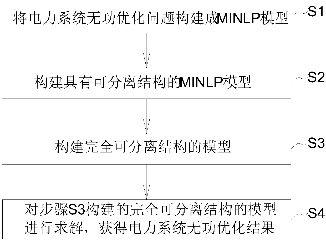
[0092] refer to figure 1 As shown, the flow chart of the decomposition method for solving the reactive power optimization of the discrete control power system provided by this embodiment, the method specifically includes the following steps:

[0093] S1. Constructing the power system reactive power optimization problem into a MINLP model; wherein, the MINLP model is described as follows:

[0094]

[0095] s.t.g(u c , u d ,x)=0 (1b)

[0096] u cmin ≤u c ≤u cmax (1c)

[0097] u dmin ≤u d ≤u dmax (1d)

[0098] x min ≤x≤x max (1e)

[0099] Among them: f(u c , u d , x) represents the active power loss of the whole network; formula (1b) represents the nonlinear power flow equation; formulas (1c)-(1e) represent the upper and lower bound constraints of continuous control variables, discrete control variables and state variables respectively; u c =V g Represents a column vector of continuous control variables; u d =[Q B ; k T ] represents the column vector of ...


PUM


Abstract

The present invention discloses a decomposition method of solving discrete control-containing electric power system reactive optimization. The method comprises the following steps of S1 constructing an electric power system reactive optimization problem into a mixed-integer nonlinear programming (MINLP) model; S2 constructing the MINLP model having a separable structure; S3 constructing a model ofa totally separable structure; S4 solving the model of the totally separable structure to obtain an electric power system reactive optimization result. According to the method of the present invention, firstly the electric power system reactive optimization problem is constructed into the MINLP model, the model does not have the special requirements for a grid structure, is suitable for a mediumand low voltage power distribution network having the radiativity, is also suitable for a complex high voltage large grid and is wide in applicability; then by copying the discrete control variables,allowing one discrete control variable in the model to change continuously, at the same time, increasing the consistency constraint between the discrete control variables and the discrete control variable changing continuously, the original problem has the separable structure besides the consistency constraint, and the optimization result can be obtained more rapidly and accurately.

Description

technical field [0001] The present invention and a reactive power optimization method of a power system specifically relate to a decomposition method for solving reactive power optimization of a power system with discrete control. Background technique [0002] The problem of reactive power optimization in power systems refers to reducing the active power loss of the power grid by adjusting the terminal voltage of the generator, the output of capacitors / reactors, and the transformation ratio of the on-load tap changer, and satisfying various physical and operational constraints. Due to the discrete nature of capacitor / reactor output and transformer ratio, and the strong nonlinearity of the power flow equation, this problem can be described as a MINLP problem in mathematics. This problem is very difficult to solve, and may even be an NP-hard problem. [0003] At present, the methods for solving reactive power optimization problems with discrete control mainly include: model c...

Claims


Application Information

Patent Timeline
IPC IPC(8): H02J3/16
CPCY02E40/30
Inventor 刘明波郑佳滨陆文甜王志军谢敏朱建全
Owner SOUTH CHINA UNIV OF TECH
Learn More