Steel tube cutting equipment with automatic discharging function

A technology for automatic unloading and cutting equipment, which is applied in the direction of shearing machine equipment, metal processing equipment, pipe shearing devices, etc. It can solve the problems of inconvenient unloading and transportation, and achieve the effect of convenient operation, simple equipment structure, and stable movement

Inactive Publication Date: 2018-01-19
赵顺豪
View PDF0 Cites 15 Cited by
  • Summary
  • Abstract
  • Description
  • Claims
  • Application Information

AI Technical Summary

Problems solved by technology

[0005] Aiming at the deficiencies of the prior art, the present invention provides a steel pipe cutting equipment with automatic unloading functio

Method used


Image

  • Steel tube cutting equipment with automatic discharging function
  • Steel tube cutting equipment with automatic discharging function
  • Steel tube cutting equipment with automatic discharging function

Examples


Embodiment Construction

[0030] The following will clearly and completely describe the technical solutions in the embodiments of the present invention with reference to the accompanying drawings in the embodiments of the present invention. Obviously, the described embodiments are only some, not all, embodiments of the present invention. Based on the embodiments of the present invention, all other embodiments obtained by persons of ordinary skill in the art without making creative efforts belong to the protection scope of the present invention.

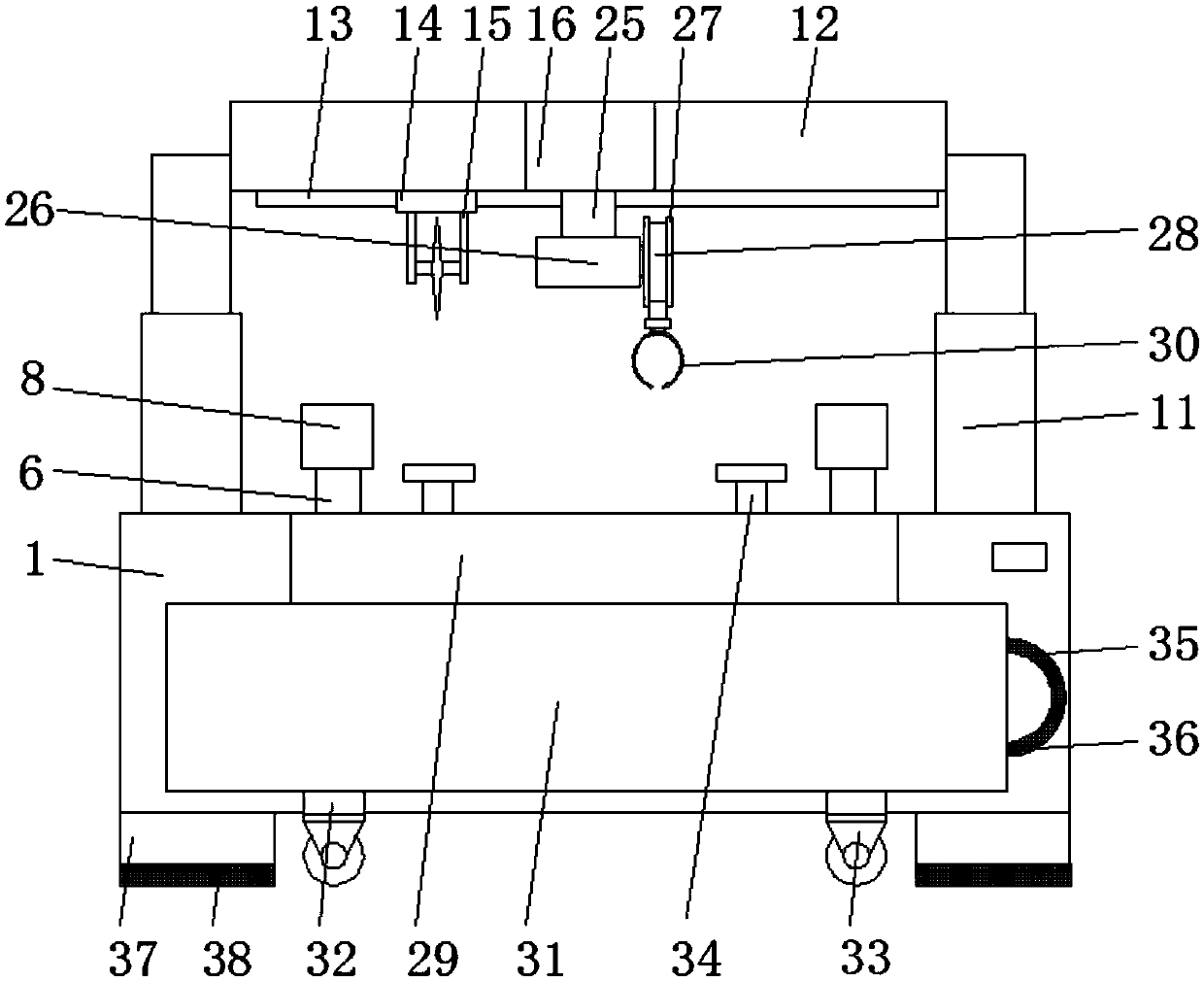
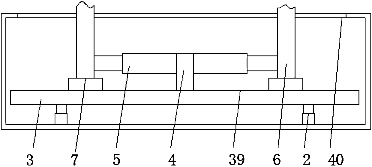
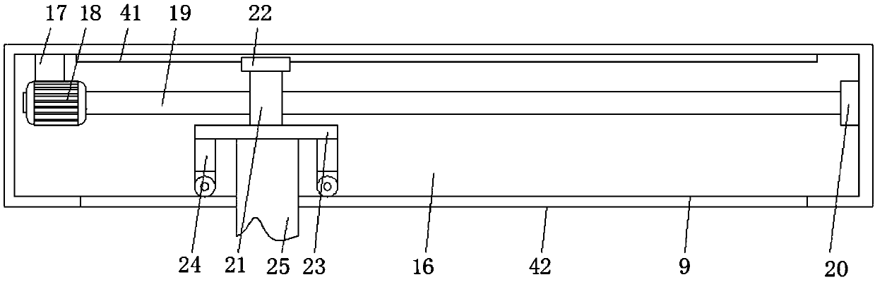
[0031] The embodiment of the present invention provides a kind of steel pipe cutting equipment with automatic unloading function, such as Figure 1-5As shown, including the workbench 1, the bottom of the workbench 1 is fixedly connected with a placement seat 37, and the bottom of the placement seat 37 is provided with anti-skid lines 38. The role of the grooves 38 achieves a more stable placement of the workbench 1, thereby facilitating the unloading of steel ...


PUM


Abstract

The invention provides steel tube cutting equipment with an automatic discharging function and relates to the field of mechanical equipment. The steel tube cutting equipment with the automatic discharging function comprises a workbench. The bottom of the inner wall of the workbench is fixedly connected with damping cushions. The tops of the damping cushions are fixedly connected with a supportingplate. The top of the supporting plate is fixedly connected with a connection block. The two sides of the connection block are fixedly connected with first power-driven telescopic rods. According to the steel tube cutting equipment with the automatic discharging function, by means of a steel tube collection box arranged on the front side of the workbench and the moving of a moving rod, the effectthat a steel tube on a steel tube clamping device is driven to move into the steel tube collection box is achieved; and by means of the arrangement of universal wheels on the bottom of the steel tubecollection box, the effect the steel tube collection box is moved more conveniently with less labor is achieved, and the problem that in the manufacture and production process of the steel tubes, thecut steel tubes are discharged and carried not conveniently is solved.

Description

technical field [0001] The invention relates to the technical field of mechanical equipment, in particular to a steel pipe cutting equipment with automatic unloading function. Background technique [0002] The development of steel pipe production technology began with the rise of the bicycle manufacturing industry, the development of petroleum in the early 19th century, the manufacture of ships, boilers, and aircraft during the two world wars, the manufacture of thermal power boilers after the Second World War, the development of the chemical industry and The drilling and transportation of oil and natural gas have all strongly promoted the development of the steel pipe industry in terms of variety, output and quality. Steel pipes are not only used to transport fluids and powdery solids, exchange heat, and manufacture mechanical parts and containers. economical steel. Using steel pipes to manufacture building structure grids, pillars and mechanical supports can reduce weight...

Claims


Application Information

Patent Timeline
IPC IPC(8): B23D21/00B23D33/04B23Q1/01B23Q1/25B23Q5/28B23Q11/00B21D43/20
Inventor 赵顺豪
Owner 赵顺豪
Why Eureka
Try Eureka