
Bionic step-by-step compaction type ridging shaper

A technology of shaping machine and shaping board, applied in planting methods, agricultural machinery and implements, plows, etc., can solve problems such as inability to remove soil, difficult ridge body strength, and inconvenience in cleaning and processing equipment.

Inactive Publication Date: 2021-04-20
郑秀琴
View PDF0 Cites 0 Cited by
  • Summary
  • Abstract
  • Description
  • Claims
  • Application Information

AI Technical Summary

Problems solved by technology

However, with the rapid development of agricultural technology and the continuous improvement of agronomic planting requirements, the deficiencies in the actual use of ridging equipment also urgently need to be improved.
[0003] At present, the common ridging equipment on the market is mainly the plow, and the auxiliary shaping device is added. When the equipment is in operation, due to the turning effect of the coulter, the soil plowed by the coulter can be accumulated between the two coulters, reaching However, in the actual shaping and compacting process of this kind of ridging equipment, it is difficult to ensure that the ridge body reaches a reasonable strength, and it is difficult for the germination and rooting of seeds and the water absorption and moisture conservation of the soil. At the same time, the coulter and the shaping device cannot remove the soil adhered to the equipment in actual work, which increases the resistance consumption of the equipment during operation, and is not convenient for the operator to clean the equipment in the future.

Method used


Image

  • Bionic step-by-step compaction type ridging shaper
  • Bionic step-by-step compaction type ridging shaper
  • Bionic step-by-step compaction type ridging shaper

Examples


Embodiment 1

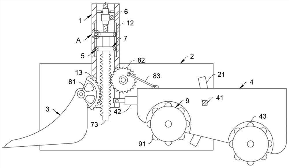
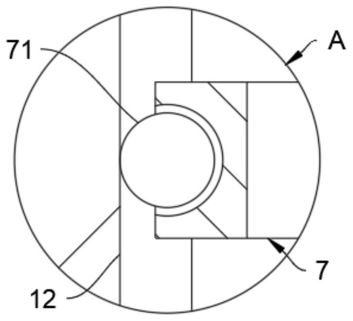
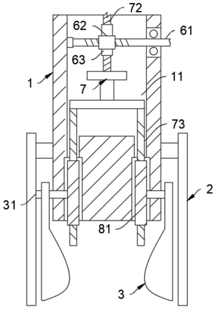
[0028] Such as Figure 1-4 As shown, a bionic step-by-step compaction ridge shaping machine includes a frame 1, and the frame 1 is symmetrically welded with a material retaining plate 2. It should be noted that the frame 1 is directly connected to driving equipment such as a tractor. To facilitate the assembly and disassembly of the device, the material retaining plate 2 adopts a rectangular structure, which is convenient for the shaping of the shaping plate 4 by blocking the plowed soil during the working process of the coulter 3 .

[0029] One end of the baffle plate 2 close to the frame 1 is rotatably connected with a coulter 3 , and the other end of the baffle plate 2 close to the frame 1 is slidably connected with a shaping plate 4 , and the frame 1 drives the coulter 3 and the shaping plate 4 through the transmission assembly 5 For ridging and shaping work, it should be noted that the coulter 3 adopts a curved surface structure, and the symmetrical mirror images are arra...

Embodiment 2

[0041] for Figure 5 The second shown embodiment is different from the first embodiment:

[0042] The blade surface of the coulter 3 is provided with multiple sets of scraping grooves 32, and the scraping grooves 32 are slidably connected with a scraper 34 through a spring 33. The middle part of the scraper 34 adopts a prismatic structure. It is worth mentioning that the length dimension of the scraper 34 is It is larger than the opening length of the scraper 32 to prevent soil from entering the scraper 32. By setting the prismatic scraper 34, not only the ridging effect of the coulter 3 is improved, but also the coulter 3 is retracted by the spring 33 The stretching makes the scraper 34 slide and scrape the curved surface of the coulter 3, reducing the adhesion of soil to the surface of the coulter 3, and improving the subsequent cleaning effect of the operator.


PUM


Abstract

The invention belongs to the technical field of agricultural equipment, and particularly relates to a bionic step-by-step compaction type ridging shaper. The shaper comprises a rack, striker plates are symmetrically welded to the rack, coulters are rotatably connected to the ends, close to the rack, of the striker plates, and shaping plates are slidably connected to the other ends, close to the rack, of the striker plates. The rack drives the coulters and the shaping plates to conduct ridging and shaping work through a transmission assembly, and the transmission assembly comprises a driving piece, a movable frame and a transmission piece. The ridging shaper is provided with the shaping plates which are compacted step by step, so that the ridging shaper can perform step-by-step compaction work on a ridge body in actual work, the compaction effect of the ridge body in the ploughing process of the coulters is improved, then the germination and rooting effects of seeds and the water absorption and soil moisture conservation effects of soil are improved, and meanwhile, the shaping plates have an automatic discharging function; and the situation that a shaping roller adheres to soil in the long-term working process is avoided, resistance consumption during equipment operation is reduced, and the cleaning efficiency of operators is improved.

Description

technical field [0001] The invention belongs to the technical field of agricultural equipment, in particular to a bionic step-by-step compacting type ridging and shaping machine. Background technique [0002] The ridging machine is one of the common equipment in the agricultural planting process. It has the characteristics of easy adjustment of ridge distance, ridge height, number of ridge rows, and angle, wide supporting range, and strong adaptability. It has the advantages of saving fertilizer, drainage and waterlogging, moisture conservation and water storage, and increasing soil moisture. It is mainly suitable for potatoes, beans, and vegetable crops. However, with the rapid development of agricultural technology and the continuous improvement of agronomic planting requirements, the deficiencies in the actual use of ridging equipment also urgently need to be improved. [0003] At present, the common ridging equipment on the market is mainly the plow, and the auxiliary s...

Claims


Application Information

Patent Timeline
Patent Type & Authority Applications(China)
IPC IPC(8): A01C5/06A01B13/02A01B15/20
Inventor 郑秀琴
Owner 郑秀琴
Learn More