
Cantilever folding mechanism of electric unmanned aerial vehicle

An electric unmanned aerial vehicle and folding mechanism technology, applied in the field of unmanned aerial vehicles, can solve the problems of low reliability, looseness, and relative displacement easily, and achieve the effect of improving connection reliability.

Pending Publication Date: 2018-01-19
沈阳旋飞航空技术有限公司
View PDF10 Cites 13 Cited by
  • Summary
  • Abstract
  • Description
  • Claims
  • Application Information

AI Technical Summary

Problems solved by technology

There is a problem in these folding mechanisms of the prior art, that is, the positioning between the first part and the second part is basically carried out by the rotating shaft. Because the rotating shaft will rotate relative to these two parts, there will always be a certain gap. The relative displacement between the two parts where the rotating shaft is positioned is easy to occur, so other connection methods such as bolts have to be considered for reinforcement. In addition, the force generated by the displacement of these two parts will be transmitted to the detachable structure. It will make the detachable structure loose, because the detachable structure is originally used to facilitate connection and detachment. Preventive reinforcement leads to complex structure, heavy weight and relatively low reliability of these existing folding mechanisms

Method used


Image

  • Cantilever folding mechanism of electric unmanned aerial vehicle
  • Cantilever folding mechanism of electric unmanned aerial vehicle
  • Cantilever folding mechanism of electric unmanned aerial vehicle

Examples


Embodiment Construction

[0021] In order to have a clearer understanding of the technical features, purposes and effects of the present invention, the specific implementation manners of the present invention will now be described with reference to the accompanying drawings. Wherein, the same parts adopt the same reference numerals.

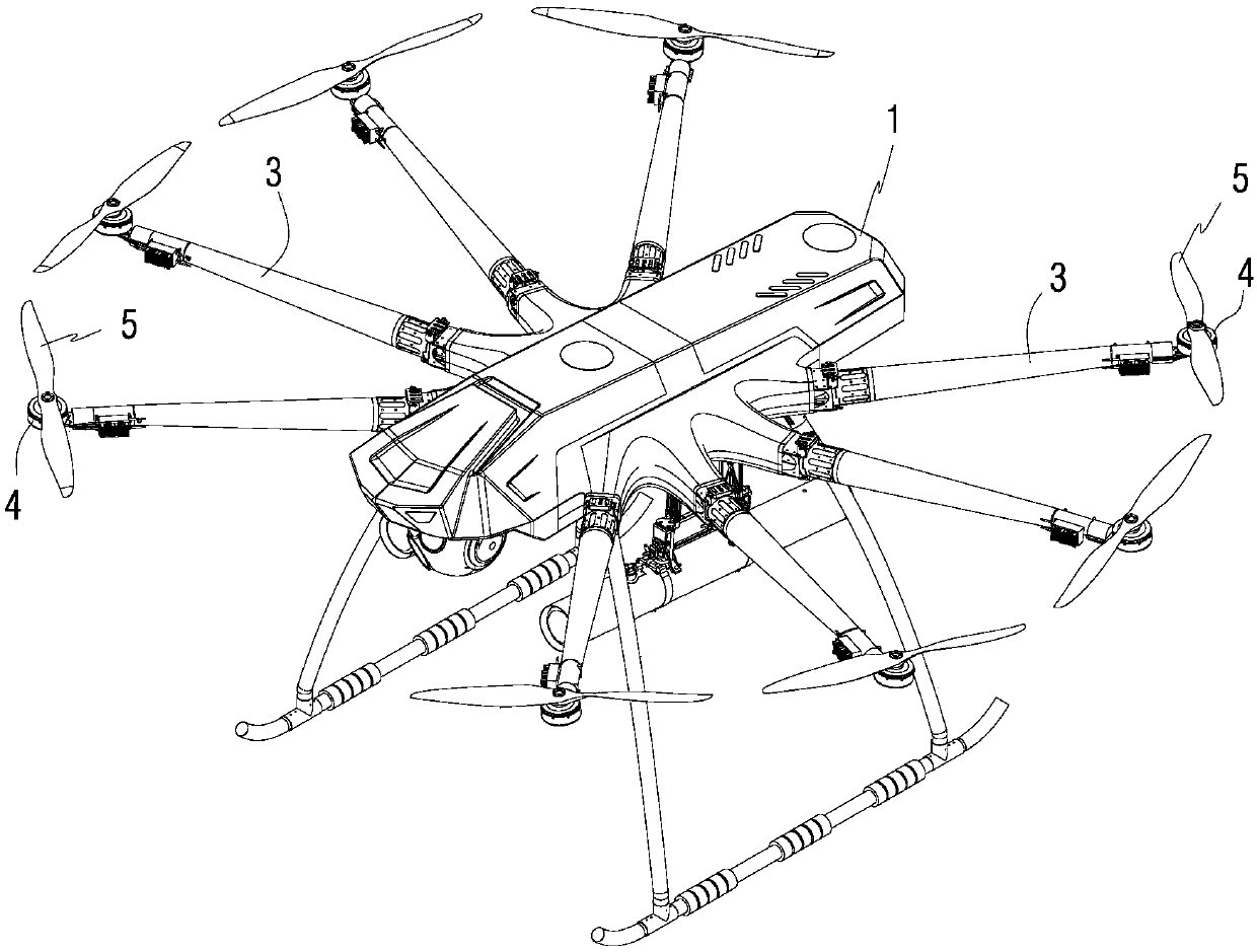
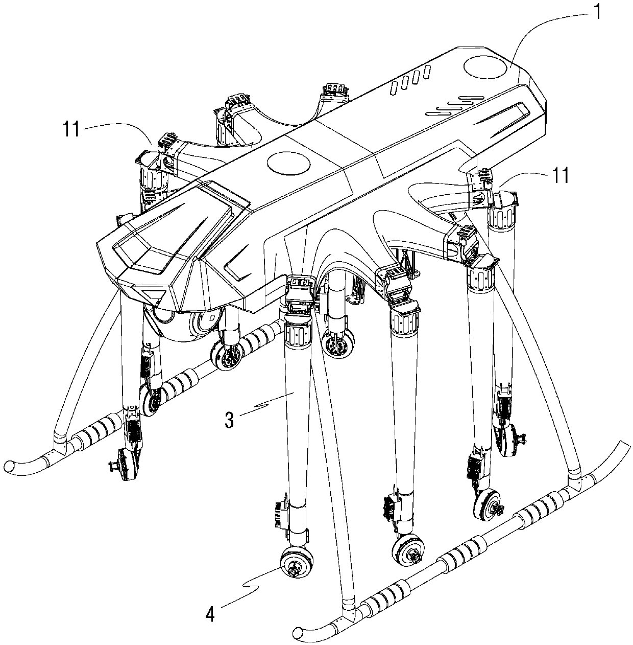
[0022] The existing multi-axis UAVs mentioned in the background technology section all adopt a fully symmetrical layout, resulting in the concentration of the center of gravity at one point, and the load layout is greatly restricted. All of them are blocked, so that the carried load cannot launch weapons or observe obliquely upwards, which limits the application range of existing drones. Based on this, the application provides an electric drone, such as figure 1 and 2 As shown, among them, figure 1 Shown is a schematic diagram of the three-dimensional structure of an electric drone according to a specific embodiment of the present invention; figure 2 to show figure ...


PUM


Abstract

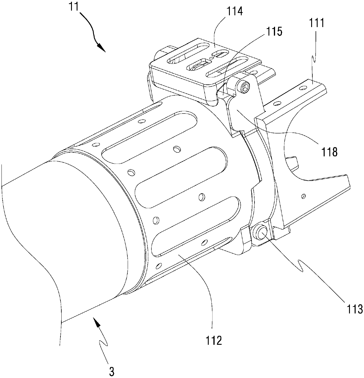
The invention relates to a cantilever folding mechanism of an electric unmanned aerial vehicle. The cantilever folding mechanism comprises a first part, a second part, a rotating shaft and an elastichook, wherein the first part is connected with a vehicle body of the electric unmanned aerial vehicle; the second part is connected with a cantilever of the electric unmanned aerial vehicle; the rotating shaft is used for connecting the first part and the second part together; the elastic hook is used for connecting the first part and the second part together; the first part is provided with a first concave part and a first convex part relative to the second part; the second part is provided with a second concave part and a second convex part relative to the first part; and the shape of the first concave part corresponds to that of the second convex part, and the shape of the second concave part corresponds to that of the first convex part. According to the cantilever folding mechanism disclosed by the invention, through the closing of convex-concave structures, a meshing relation is formed, so that the possibility that malposition is generated in a circumferential direction is avoided, and adding external reinforcing weight is not needed; and the connection of a detachable structure cannot be influenced, and the connecting reliability of the folding mechanism is improved.

Description

technical field [0001] The invention relates to the technical field of unmanned aerial vehicles, in particular to a multi-rotor electric unmanned aerial vehicle, and in particular to a cantilever folding mechanism of the electric unmanned aerial vehicle. Background technique [0002] Multi-rotor electric UAV is an unmanned aerial vehicle with multiple cantilevers. It has the advantages of simple structure, low noise, flexible maneuverability, fast response, and low operation requirements. It is widely used in agricultural plant protection, forest fire monitoring, aerial Photography, land surveying, post-disaster damage assessment and other tasks. [0003] Most of the current electric UAVs are multi-axis UAVs, such as four-axis and six-axis, etc. The take-off weight of the whole machine is very small, but the cantilever is very large, which brings certain advantages to the transportation, carrying and storage of UAVs. difficulty. Therefore, in order to improve the portabili...

Claims


Application Information

Patent Timeline
IPC IPC(8): B64C1/06B64C1/30
Inventor 刘新民鲁明张建飞孙卫华宗宁庞振岳
Owner 沈阳旋飞航空技术有限公司
Learn More