Suspension arm rotary shaft device of hot braising tank

A technology of a rotating shaft device and a boom, which is applied in the field of hot stuffy tanks, and can solve problems such as tank lids that are easy to sink, and achieve the effects of avoiding sinking, simple structure, and convenient installation

Active Publication Date: 2018-01-19
MCC ENERGY SAVING & ENVIRONMENTAL PROTECTION
View PDF5 Cites 0 Cited by
  • Summary
  • Abstract
  • Description
  • Claims
  • Application Information

AI Technical Summary

Problems solved by technology

The hinged tank lid is more commonly used in the prior art. The defect of this kind of hinged tank lid is that the tank lid is easy to sink after a period of use

Method used


Image

  • Suspension arm rotary shaft device of hot braising tank
  • Suspension arm rotary shaft device of hot braising tank
  • Suspension arm rotary shaft device of hot braising tank

Examples


Embodiment Construction

[0023] The following is a further detailed description of a boom shaft device for a hot stuffy tank according to the present invention through specific embodiments.

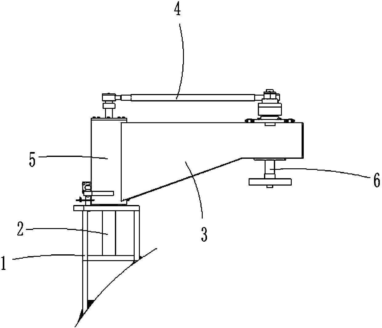
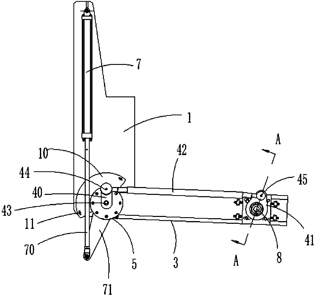
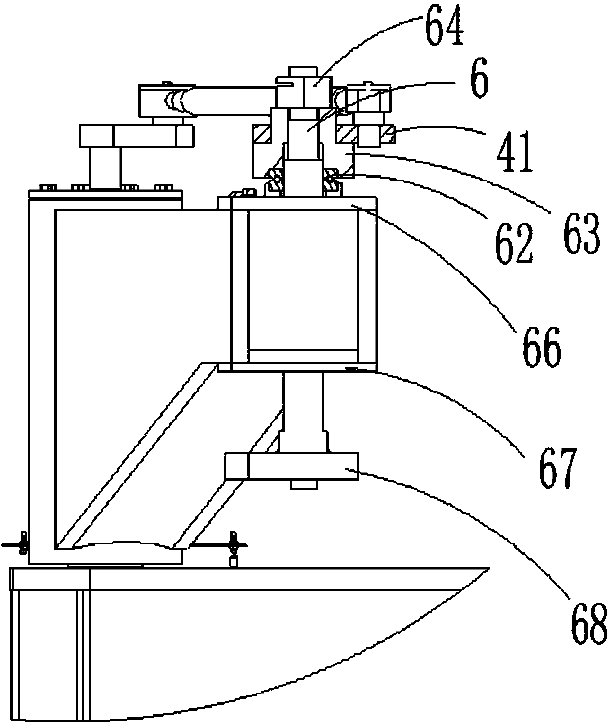
[0024] Such as figure 1 and figure 2 As shown, a boom shaft device for a hot stuffy tank includes: a boom mounting seat 1 arranged on a hot stuffy tank cylinder, a boom 3 mounted on the boom mounting seat 1 through a boom support shaft 2 and The link mechanism 4 installed on the boom 3, the boom shaft mechanism 5 is arranged between the boom 3 and the boom support shaft 2, the can lid shaft fixedly connected with the can lid is installed in the boom 3 6. The boom mounting seat 1 is equipped with a hydraulic cylinder 7 for driving the boom shaft mechanism 5 to rotate, and the piston rod 70 of the hydraulic cylinder 7 is connected with the boom shaft mechanism 5 through a connecting piece 71. The mounting base 1 is provided with a proximity switch mounting plate 10, and the proximity switch mounting plate 10 is ...


PUM


Abstract

The invention relates to a suspension arm rotary shaft device of a hot braising tank. The suspension arm rotary shaft device comprises a suspension arm mounting base, a suspension arm and a connectingrod mechanism. A suspension arm rotary shaft mechanism is arranged between the suspension arm and a suspension arm supporting shaft. A tank cover rotary shaft fixedly connected with the fixing tank is mounted in the suspension arm. The connecting rod mechanism comprises a first connecting rod fixing plate, a second connecting rod fixing plate and a connecting rod connected between the first connecting rod fixing plate and the second connecting rod fixing plate. The first connecting rod fixing plate is fixedly connected with the suspension arm supporting shaft. The first connecting rod fixingplate is connected with the connecting rod through a first rotary connection mechanism. The second connecting rod fixing plate is fixedly connected with the tank cover rotary shaft. The connecting rodis connected with the second connecting rod fixing plate through a second rotary connection mechanism. A hydraulic cylinder used for driving the suspension arm rotary shaft mechanism to rotate is mounted on the suspension arm mounting base. A piston rod of the hydraulic cylinder is connected with the suspension arm rotary shaft mechanism through a connecting part, and thus the tank cover can be prevented from sinking.

Description

【Technical field】 [0001] The invention relates to a hot stuffy tank, in particular to a boom rotating shaft device for a hot stuffy tank. 【Background technique】 [0002] Steel slag is an inevitable by-product in the steelmaking process, and its discharge accounts for about 15-20% of the crude steel output. The utilization rate of steel slag in my country is low at present. In recent years, my country's steel industry has developed rapidly. According to statistics, in 2008 my country The output of crude steel reaches 500 million tons, and the annual steel output reaches 50-100 million tons. Reasonable utilization and effective recycling of steel slag is a key to realize the sustainable development of the steel industry, solve the shortage of steel scrap in steel enterprises, reduce production costs, and improve the economic benefits of enterprises. Important measures are also favorable measures to protect the environment, reduce pollution, and turn waste into wealth. [0003] ...

Claims


Application Information

Patent Timeline
Patent Type & Authority Applications(China)
IPC IPC(8): C21B3/10
CPCY02W30/50
Inventor 田晓林何雪艳毛海峰
Owner MCC ENERGY SAVING & ENVIRONMENTAL PROTECTION
Why Eureka
Try Eureka