Inserted heat-isolating and cooling mechanism for high-temperature draught fan
A heat insulation and cooling, plug-in technology, applied in the direction of machines/engines, mechanical equipment, non-variable pumps, etc., can solve the problems of reducing the life of the fan and the short distance between the driving mechanism and the heat insulation layer, so as to improve the life of the fan, The effect of reducing temperature and blocking heat transfer
- Summary
- Abstract
- Description
- Claims
- Application Information
AI Technical Summary
Problems solved by technology
Method used
Image

Examples
Embodiment Construction
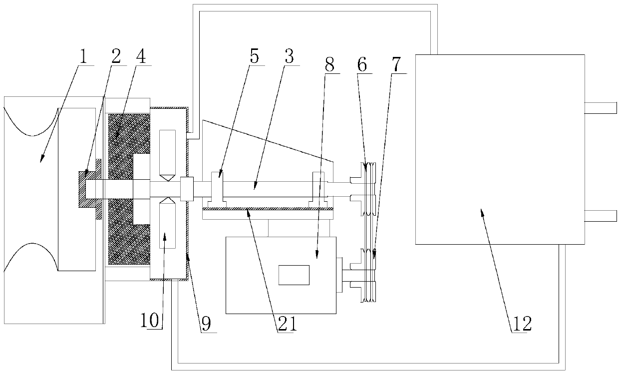
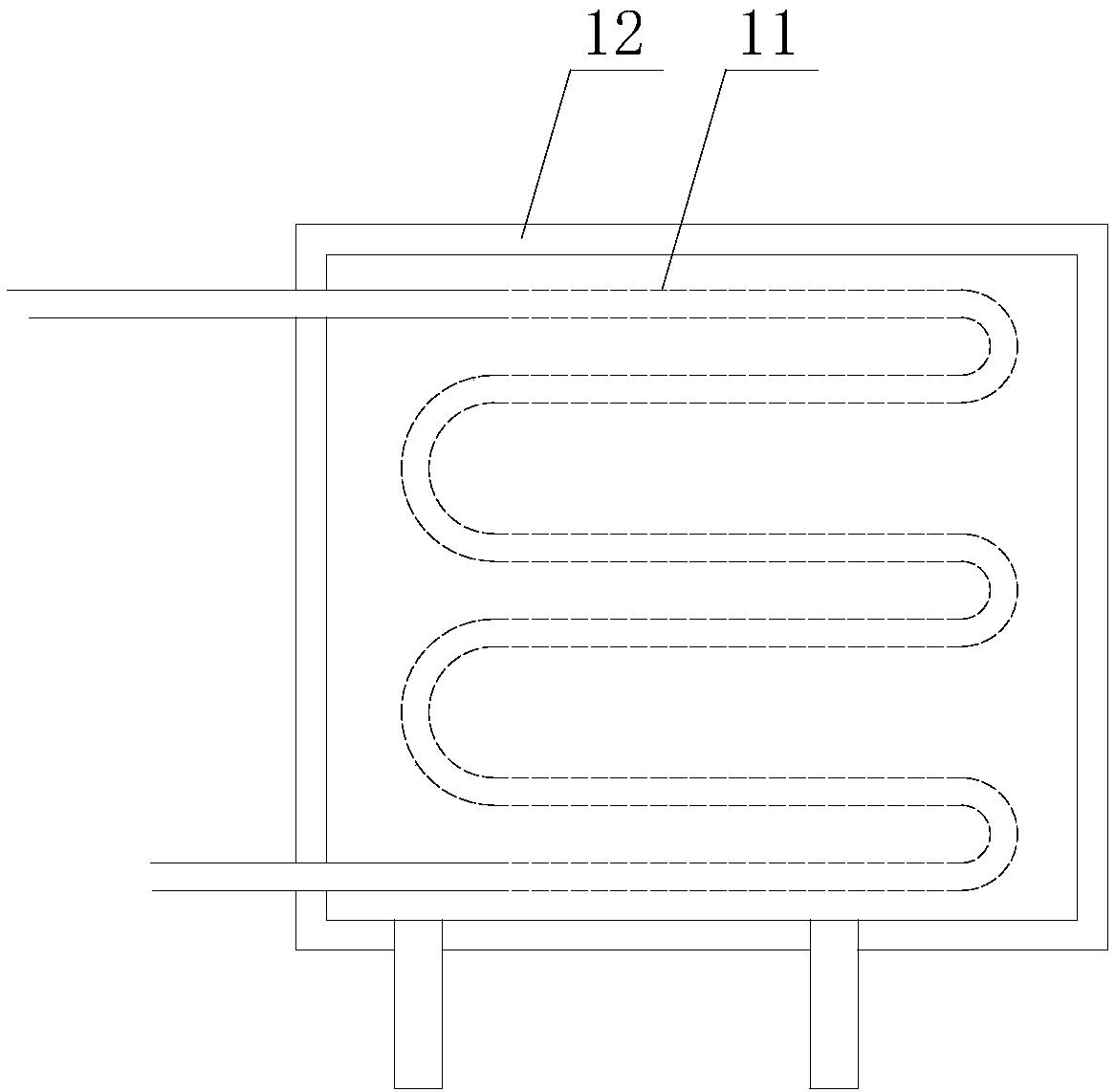
[0013] Attached below Figure 1-2 An embodiment of the present invention is described.
[0014] A heat insulation and cooling mechanism for a plug-in high-temperature fan, including a heat dissipation mechanism, a heat insulation mechanism, a heat resistance mechanism and a driving mechanism. The heat dissipation mechanism includes a heat dissipation volute 1 arranged in a pipeline, and a heat dissipation impeller is arranged in the heat dissipation volute , the heat dissipation impeller is installed on the impeller seat 2, the impeller seat 2 is installed on the front end of the main shaft 3, and the outer surface of the pipe near the main shaft 3 is provided with a heat insulation layer 4;
[0015] The rear end of the main shaft 3 is connected to the drive mechanism, the main shaft 3 is installed on the frame 21 through two bearing blocks 5, the rear end of the main shaft 3 is equipped with a driven pulley 6, and the driven pulley 6 and the driving pulley 7 are connected by ...
PUM
 Abstract
Description
Claims
Application Information
 - R&D
- Intellectual Property
- Life Sciences
- Materials
- Tech Scout
- Unparalleled Data Quality
- Higher Quality Content
- 60% Fewer Hallucinations
Browse by: Latest US Patents, China's latest patents, Technical Efficacy Thesaurus, Application Domain, Technology Topic, Popular Technical Reports.
© 2025 PatSnap. All rights reserved.Legal|Privacy policy|Modern Slavery Act Transparency Statement|Sitemap|About US| Contact US: help@patsnap.com