
Air spring device driven by linear motor

A linear motor and gas spring technology, applied in the field of springs, can solve the problems of limitation of the electric drive mechanism of the tailgate, unstable operation, large equipment volume, etc., and achieve the effects of low manufacturing difficulty, wide application range and fast response speed.

Active Publication Date: 2018-01-19
NINGBO INST OF TECH ZHEJIANG UNIV ZHEJIANG +2
View PDF6 Cites 1 Cited by
  • Summary
  • Abstract
  • Description
  • Claims
  • Application Information

AI Technical Summary

Problems solved by technology

[0005] The electric drive mechanism for the tailgate of the automobile directly installs the stator and mover of the linear motor on the cylinder body of the ordinary gas spring. In order to give full play to the advantages of the strong designability of the structure of the linear motor, the electric drive mechanism for the tailgate of the automobile has equipment At the same time, due to the interference of ordinary gas springs, that is, when the linear motor drives the gas spring piston rod to move, the air pressure in the gas spring piston rod cavity and rodless cavity will change accordingly, resulting in the electric drive mechanism of the tailgate of the car. The operation is not stable; in summary, due to these defects, the application and promotion of the electric drive mechanism for the tailgate of the car is limited, and no specific products have been seen on the market

Method used


Image

  • Air spring device driven by linear motor
  • Air spring device driven by linear motor
  • Air spring device driven by linear motor

Examples


Embodiment Construction

[0034] The preferred embodiments of the present invention will be described in detail below with reference to the accompanying drawings.

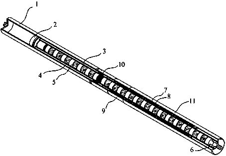
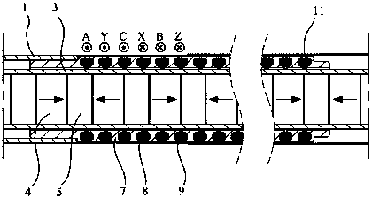
[0035] Such as figure 1 Shown is a schematic structural view of an embodiment of a gas spring device driven by a linear motor in the present invention. The gas spring device driven by the linear motor of the present embodiment comprises a cylinder liner with an open end, the cylinder liner is provided with a connecting rod 3 which fits with the gap and is made of non-magnetic material, and one end of the connecting rod 3 extends out of the cylinder liner. Outside the opening, a central through hole is provided in the connecting rod 3, and a magnetic force unit is set in the central through hole. The magnetic force unit includes magnets 4 and magnetizers 5 arranged at intervals. One end of the connecting rod 3 located in the cylinder liner is fixedly connected with the piston 2 provided, and the end of the connecting rod 3 extending out of ...


PUM


Abstract

The invention discloses an air spring device driven by a linear motor. The air spring device comprises an air cylinder sleeve with one open end. The air cylinder sleeve is internally provided with a connecting rod which is in clearance fit with the air cylinder sleeve and made of a non-permeability magnetic material. One end of the connecting rod extends out of an opening of the air cylinder sleeve, the connecting rod is internally provided with a center through hole, and a magnetic force unit is sleeved with the center through hole. The magnetic force unit comprises magnets and magnetizers which are alternately arranged. The end, located in the air cylinder sleeve, of the connecting rod is fixedly connected with an arranged piston, the end, extending out of the air cylinder sleeve, of theconnecting rod is provided with a tail cap which is used for compressing the magnetic force unit, and the piston and the air cylinder sleeve are slidably matched. An iron core arranged outside the connecting rod in a sleeving mode is fixedly arranged in the air cylinder sleeve, an armature coil is arranged in the iron core, the iron core is in clearance fit with the connecting rod, and an air gapis formed between the iron core and the connecting rod. The air spring device driven by the linear motor adopts the integrated design idea and has the advantages of being simple and compact in structure, small in size, high in response speed, high in motion precision, small in friction, low in noise and the like.

Description

technical field [0001] The invention belongs to the technical field of springs, in particular to a gas spring device driven by a linear motor. Background technique [0002] Gas spring is an industrial accessory that can perform functions such as support, buffer, brake, height adjustment and angle adjustment. It is widely used in the fields of automobile, aviation, medical equipment, furniture and machinery manufacturing. In some advanced applications of automobiles, engineering machinery, and textile equipment, it is required that the gas spring can automatically expand and contract through electronic control, so as to solve the automatic control problems of different applications. [0003] At present, the common electric drive struts are mainly divided into two categories: one is a structure that adopts a steel coil spring to cooperate with a motor, a reducer, and a lead screw. Mechanism, the main problem is that the supporting force of the steel coil spring is proportion...

Claims


Application Information

Patent Timeline
Patent Type & Authority Applications(China)
IPC IPC(8): F15B15/14F15B15/20F16J7/00F16J15/16F16J1/00H02K41/03
Inventor 潘泽民屈稳太宦红伦
Owner NINGBO INST OF TECH ZHEJIANG UNIV ZHEJIANG
Learn More