Clutch control device, system and method and vehicle

A clutch control and clutch technology, applied in the field of vehicles, can solve problems such as vehicle flameout, friction plate damage, vehicle damage, etc.

Inactive Publication Date: 2018-01-19
BORGWARD AUTOMOTIVE CHINA CO LTD
View PDF4 Cites 4 Cited by
  • Summary
  • Abstract
  • Description
  • Claims
  • Application Information

AI Technical Summary

Problems solved by technology

[0004] Under normal circumstances, when the vehicle is shifting gears while driving, if the clutch pedal is released too quickly, it will easily cause the vehicle to stall; damage, and major damage to the vehicle

Method used


Image

  • Clutch control device, system and method and vehicle
  • Clutch control device, system and method and vehicle
  • Clutch control device, system and method and vehicle

Examples


Embodiment Construction

[0064] Specific embodiments of the present disclosure will be described in detail below in conjunction with the accompanying drawings. It should be understood that the specific embodiments described here are only used to illustrate and explain the present disclosure, and are not intended to limit the present disclosure.

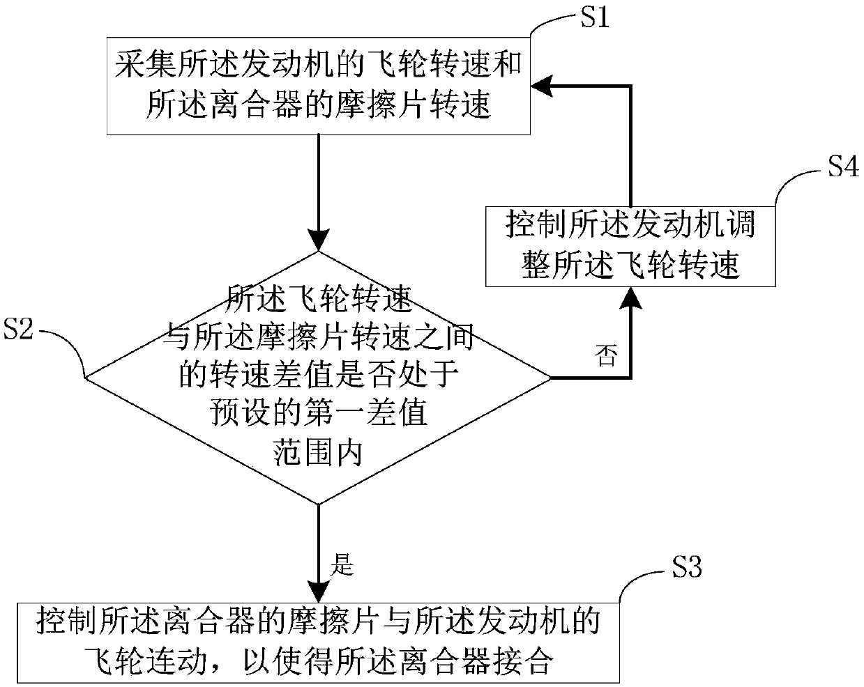
[0065] figure 1 is a flow chart of a specific embodiment of the clutch control method provided by the present disclosure, which is used to control the clutch engagement when the gear shift is completed. refer to figure 1 As shown in, the clutch control method includes the following steps:

[0066] In step S1, the flywheel speed of the engine and the friction plate speed of the clutch are collected;

[0067] In step S2, it is judged whether the rotational speed difference between the flywheel rotational speed and the friction plate rotational speed is within a preset difference range, if yes, proceed to step S3; if not, proceed to step S4.

[0068] In step...


PUM


Abstract

The invention relates a clutch control device, system and method and a vehicle. The clutch control method is used for controlling the clutch engagement when the gear shift is completed, and comprisesthe following steps of collecting the flywheel rotation speed of an engine and the friction plate rotation speed of a clutch; controlling a friction plate of the clutch to move with a flywheel of theengine in a linkage mode so as to make the clutch be engaged when the speed difference between the flywheel rotation speed and the friction plate rotation speed is within a predefined first differencerange; and controlling the engine to adjust the rotation speed of the flywheel and returning to the step of collecting the flywheel rotation speed of the engine and the friction plate rotation speedof the clutch when the rotation speed difference is not within the predefined first difference range. The clutch control method is capable of controlling the time of the clutch engagement automatically, and avoiding problems caused by too fast or too slow clutch engagement.

Description

technical field [0001] The present disclosure relates to the field of vehicle clutches, in particular, to a clutch control device, a clutch control system, a clutch control method and a vehicle. Background technique [0002] The clutch is located in the flywheel housing between the engine and the gearbox, and the clutch assembly is fixed on the rear plane of the flywheel with screws, and the output shaft of the clutch is the input shaft of the gearbox. During the driving process of the car, the driver can step on or release the clutch pedal as needed to temporarily separate the engine from the gearbox and gradually engage it, so as to cut off or transmit the power input from the engine to the gearbox. [0003] The clutch has three working states, namely disengagement, linked and semi-linked. When the vehicle starts or shifts gears, the driver depresses the clutch pedal, the movement of the clutch pedal pulls the pressure plate away from the friction plate, so that the frict...

Claims


Application Information

Patent Timeline
Patent Type & Authority Applications(China)
IPC IPC(8): F16D48/10
Inventor 裴云飞王晓峰
Owner BORGWARD AUTOMOTIVE CHINA CO LTD
Why Eureka
Try Eureka