Laser radar based robot mapping navigation system and method

A laser radar and navigation system technology, applied in navigation calculation tools, radio wave measurement systems, instruments, etc., can solve problems such as poor real-time performance, large light conditions, and large image processing capacity, achieving good stability and versatility. Good and reliable results

Inactive Publication Date: 2018-01-19
SOUTH CHINA UNIV OF TECH
View PDF7 Cites 11 Cited by
  • Summary
  • Abstract
  • Description
  • Claims
  • Application Information

AI Technical Summary

Problems solved by technology

At present, the mapping and navigation methods of robots have limitations. The GPS-based navigation system is not suitable for indoor robot navigation, and the positioning accuracy cannot meet the high requirements of robots; Huge amount of processing, poor real-time performance
In general, the current map positioning and navigation methods for robots have problems such as large light conditions, huge image processing capacity, and poor real-time performance. The implementation method is complicated and the versatility is poor.

Method used


Image

  • Laser radar based robot mapping navigation system and method
  • Laser radar based robot mapping navigation system and method
  • Laser radar based robot mapping navigation system and method

Examples


Embodiment 1

[0052] like figure 1 As shown, a laser radar-based robot mapping navigation system includes:

[0053] Mobile robots with underlying drivers;

[0054] The remote workstation is provided with a graphical user interface, connected to the robot control system through a wireless local area network, and used for remotely sending instructions for moving, scanning, mapping and navigation of the robot;

[0055] The robot control system is used to control the robot to move, scan, map and navigate according to the instructions of the remote workstation;

[0056] A lidar sensor, arranged on the robot, is used to scan the surrounding environment in 360° rotation;

[0057] Power supply system for powering robots, robot control systems, lidar sensors, and remote workstations.

[0058] Specifically, the robot includes a wheeled mobile robot, a multi-legged articulated mobile robot or a crawling robot.

[0059] The robot control system adopts a microcomputer equipped with Ubuntu Linux syst...

Embodiment 2

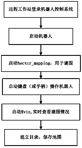
[0064] A method for robot mapping and navigation based on the system, comprising the steps of:

[0065] S1. Establishing a communication connection between the remote workstation and the robot control system based on a local area network;

[0066] S2. Start the power supply system, start the lidar and scan the surrounding environment;

[0067] S3. Control the movement of the robot through the remote workstation;

[0068] S4. The robot control system uses a mapping algorithm to construct a two-dimensional grid map of the environment and saves the constructed map in a remote workstation;

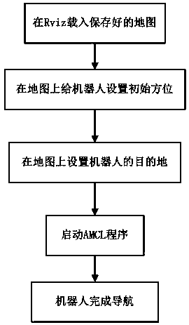
[0069] S5. Based on the constructed map, use the positioning and navigation algorithm to navigate the mobile robot.

[0070] In this embodiment, the steps S1, S2, S3, S4, and S5 are all implemented based on the Robot Operating System (ROS) platform under the Ubuntu Linux system.

[0071] Specifically, the step S1 specifically includes sub-steps:

[0072] S11. Build a router platform and cr...


PUM


Abstract

The invention discloses a laser radar based robot mapping navigation system. The system includes: a mobile robot; a remote workstation, which is connected to a robot control system through a wirelesslocal area network and is used for remote transmission of a robot's movement, scanning, mapping and navigation instructions; a robot control system, which is used for controlling the robot's movement,scanning, mapping and navigation according to the instructions of the remote workstation; a laser radar sensor, which is used for 360-degree rotation to scan the surrounding environment; and a powersupply system, which is used for power supply to the whole system. The invention also discloses a laser radar based robot mapping navigation method. The system and method provided by the invention adopts the laser radar sensor, have high stability and strong real-time performance, and are added with the remote workstation to realize human-computer interaction, fully meet the requirements of robotmapping navigation, solve the shortcomings of the prior art, have stable and reliable implementation way and good universality, and can be widely applied in robot mapping and positioning navigation field.

Description

technical field [0001] The invention relates to the field of robot mapping, positioning and navigation, in particular to a laser radar-based robot mapping and navigation system and method. Background technique [0002] With the extensive development and application of intelligent mobile robots, the requirements for their mapping, positioning and navigation are also increasing. The robot mapping and navigation system is a robot system that can obtain surrounding environment information through the sensors installed on the robot itself, fuse and analyze the information, and can independently build a map of the surrounding environment and complete positioning and navigation tasks. At present, the mapping and navigation methods of robots have limitations. The GPS-based navigation system is not suitable for indoor robot navigation, and the positioning accuracy cannot meet the high requirements of robots; The processing volume is huge and the real-time performance is poor. In ge...

Claims


Application Information

Patent Timeline
Patent Type & Authority Applications(China)
IPC IPC(8): G01C21/20G01S17/89
Inventor 韦晓琴魏武丁旭陈锐东
Owner SOUTH CHINA UNIV OF TECH
Why Eureka
Try Eureka