
Intelligent switch cabinet with extremely high performance

A switchgear and performance technology, applied in the cooling/ventilation of substation/switchgear, substation/distribution device enclosure, building lock, etc., can solve the problem that the heat dissipation performance cannot meet the needs of actual use, the safety performance is not high enough, and the practical performance Not good enough, etc., to achieve the effect of easy promotion and use, significant heat dissipation effect, and small space occupation

Inactive Publication Date: 2018-01-19
BAOHENG NEW ELECTRIC GRP
View PDF0 Cites 8 Cited by
  • Summary
  • Abstract
  • Description
  • Claims
  • Application Information

AI Technical Summary

Problems solved by technology

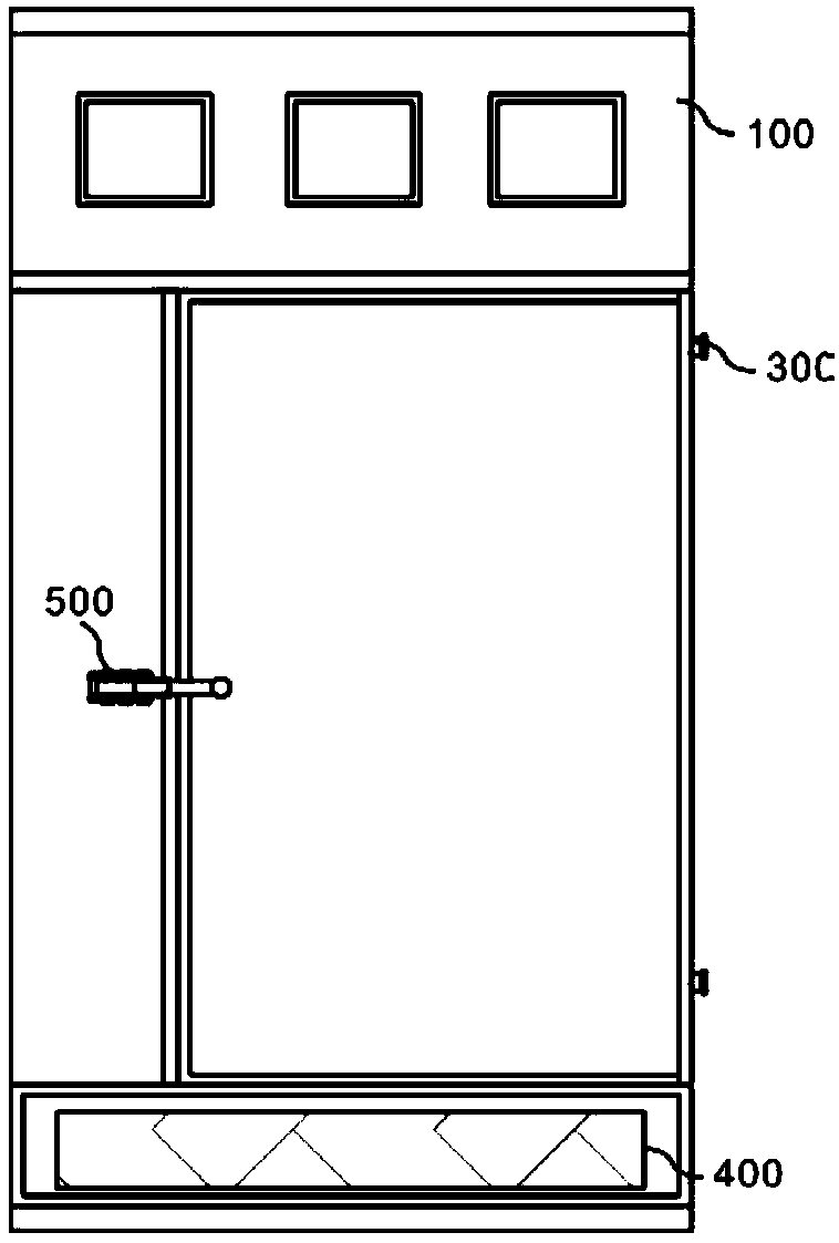
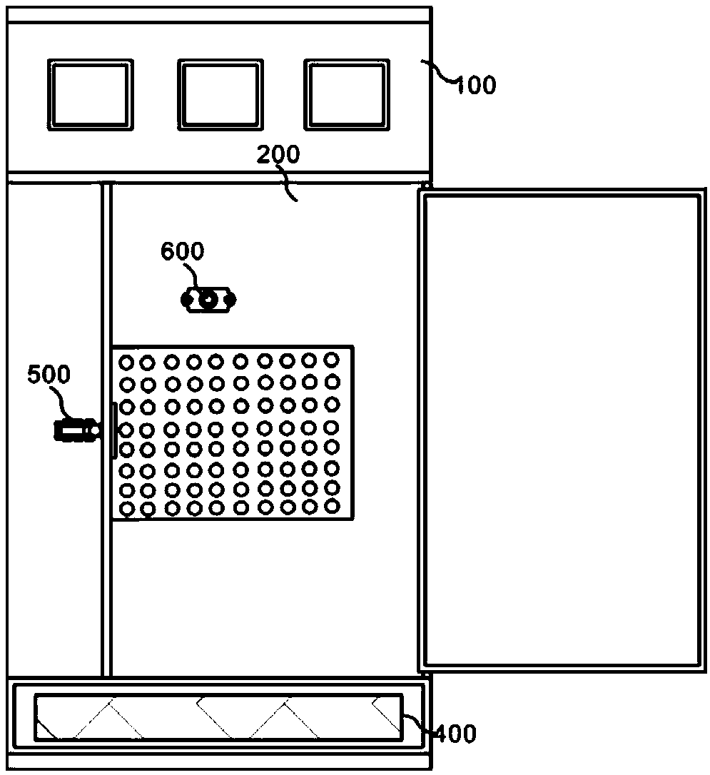
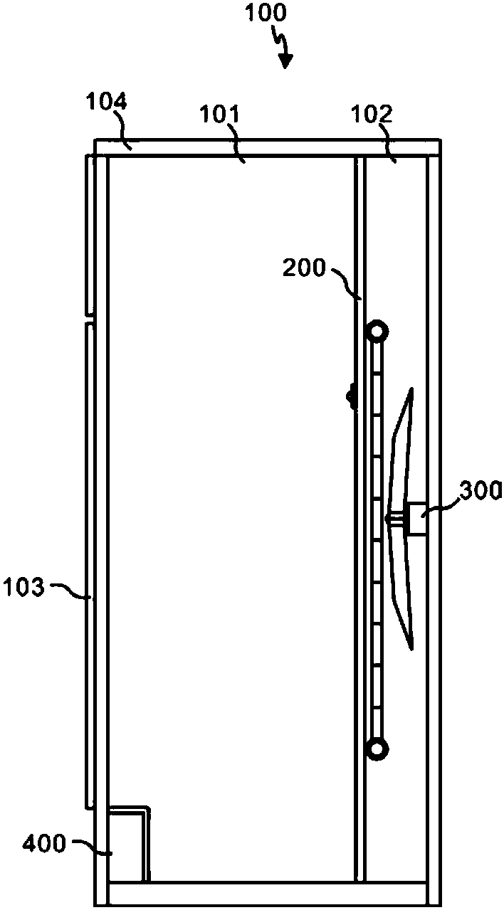
[0004] According to the needs of use, intelligent switch cabinets have appeared on the existing market. Because of their better performance, they are widely used in power plants, petroleum, chemical industry, metallurgy, textiles, high-rise buildings and other industries, as power transmission, distribution and For electric energy conversion, in recent years, people have begun to notice the performance problems of intelligent switchgear, mainly because its heat dissipation performance cannot meet the needs of actual use, wasting resources, and at the same time it cannot arrest the mice that gnaw on the wires in the intelligent switchgear , the practical performance is not good enough, and the cabinet door is easy to be reopened when the switchgear is depressurized, which is easy to accidentally injure people, and the safety performance is not high enough, which is not easy to promote and use. Therefore, we propose an intelligent switchgear with extremely high performance

Method used


Image

  • Intelligent switch cabinet with extremely high performance
  • Intelligent switch cabinet with extremely high performance
  • Intelligent switch cabinet with extremely high performance

Examples


Embodiment Construction

[0032] In order to make the above objects, features and advantages of the present invention more obvious and comprehensible, specific implementations of the present invention will be described in detail below in conjunction with the accompanying drawings.

[0033] In the following description, a lot of specific details are set forth in order to fully understand the present invention, but the present invention can also be implemented in other ways different from those described here, and those skilled in the art can do it without departing from the meaning of the present invention. By analogy, the present invention is therefore not limited to the specific examples disclosed below.

[0034] Second, "one embodiment" or "an embodiment" referred to herein refers to a specific feature, structure or characteristic that may be included in at least one implementation of the present invention. "In one embodiment" appearing in different places in this specification does not all refer to ...


PUM


Abstract

The invention discloses an intelligent switch cabinet with extremely high performance. The intelligent switch cabinet comprises a bearing assembly, a spacing assembly, a heat dissipation assembly, a capturing assembly and a self-locking assembly, wherein a first containing space and a second containing space are formed in the bearing assembly, and the first containing space is formed in one sideof the second containing space; the spaacing assembly is arranged at the boundary of the first containing space and the second containing space; the heat dissipation assembly is arranged in the secondcontaining space formed in the bearing assembly; the capturing assembly is arranged at the bottom in the first containing space of the bearing assembly; the self-locking assembly is arranged on the bearing assembly. The heat dissipation assembly arranged in a cabinet body can cool the swtich cabinet through air cooling or liquid cooling, and the heat dissipation effect is obvious; meanwhile, theheat dissipation assembly can be combined with an induction piece in use, heat dissipation can be carried out according to the temperature in the switch cabinet, the intelligent degree of the switch cabinet is further improved, and resources are also saved.

Description

technical field [0001] The invention relates to the technical field of power equipment, in particular to an intelligent switch cabinet with extremely high performance. Background technique [0002] The switch cabinet is a kind of electrical equipment. The outside line of the switch cabinet first enters the main control switch in the cabinet, and then enters the sub-control switch. Each branch is set according to its needs. Such as instruments, automatic controls, motor magnetic switches, various AC contactors, etc., some also have high-voltage room and low-voltage room switch cabinets, high-voltage busbars, such as power plants, etc. load shedding. [0003] The main function of the switchgear is to open and close, control and protect electrical equipment during the process of power generation, transmission, distribution and power conversion in the power system. The components in the switch cabinet are mainly composed of circuit breakers, disconnectors, load switches, opera...

Claims


Application Information

Patent Timeline
Patent Type & Authority Applications(China)
IPC IPC(8): H02B1/30H02B1/56H02B1/28E05B63/22
Inventor 马春洋王晓岩
Owner BAOHENG NEW ELECTRIC GRP
Learn More