Systems and methods for heart valve therapy

A technology for a valve, delivery system, applied to a prosthetic mitral valve. area for a less traumatic effect

Active Publication Date: 2018-01-19
CAISSON INT LLC
View PDF7 Cites 20 Cited by
  • Summary
  • Abstract
  • Description
  • Claims
  • Application Information

AI Technical Summary

Problems solved by technology

If the anterior leaflet is pulled too far into the LVOT, there is a risk that it interferes significantly with the outflow, creating significant clinical problems

Method used


Image

  • Systems and methods for heart valve therapy
  • Systems and methods for heart valve therapy
  • Systems and methods for heart valve therapy

Examples


Embodiment Construction

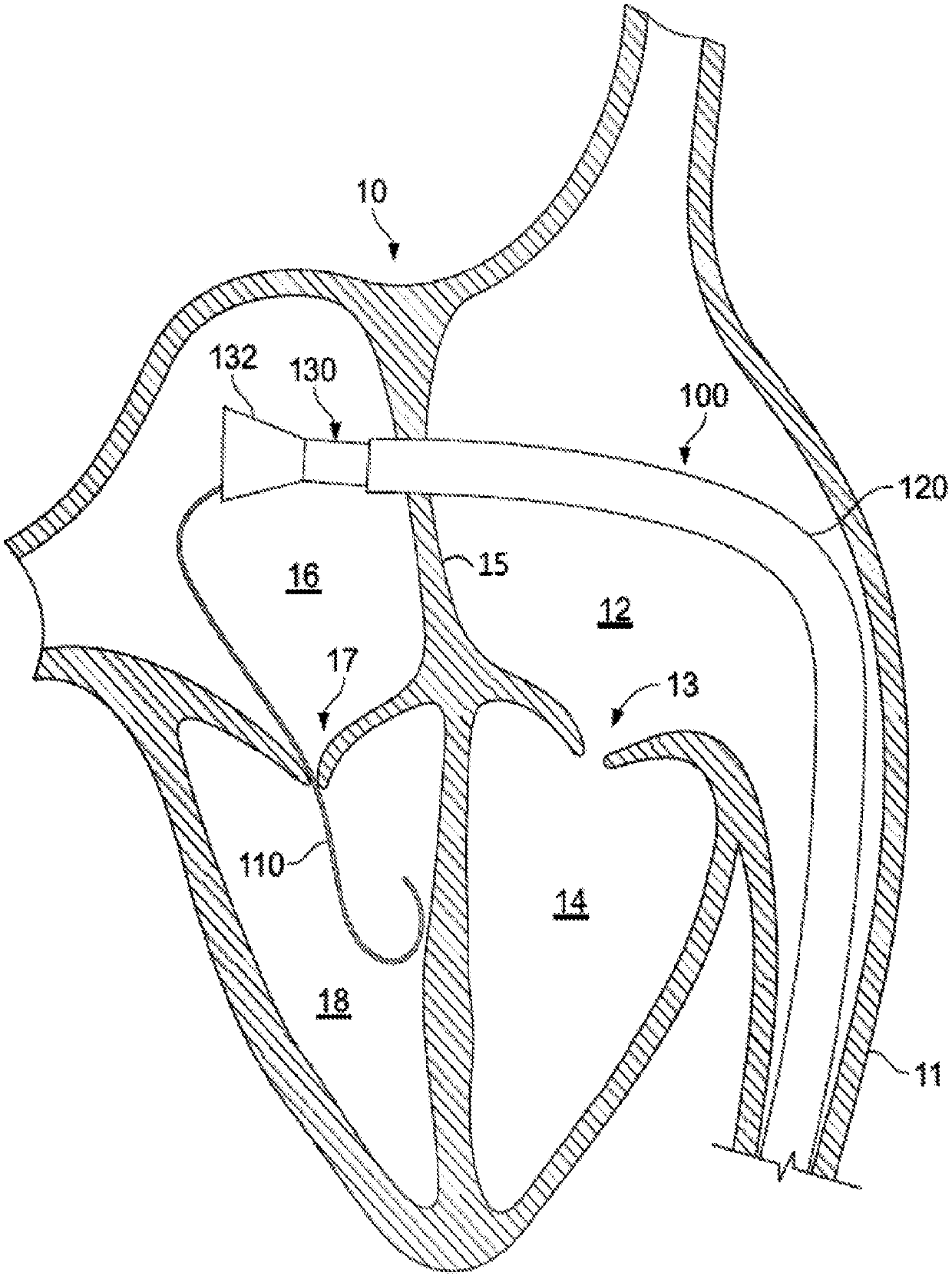
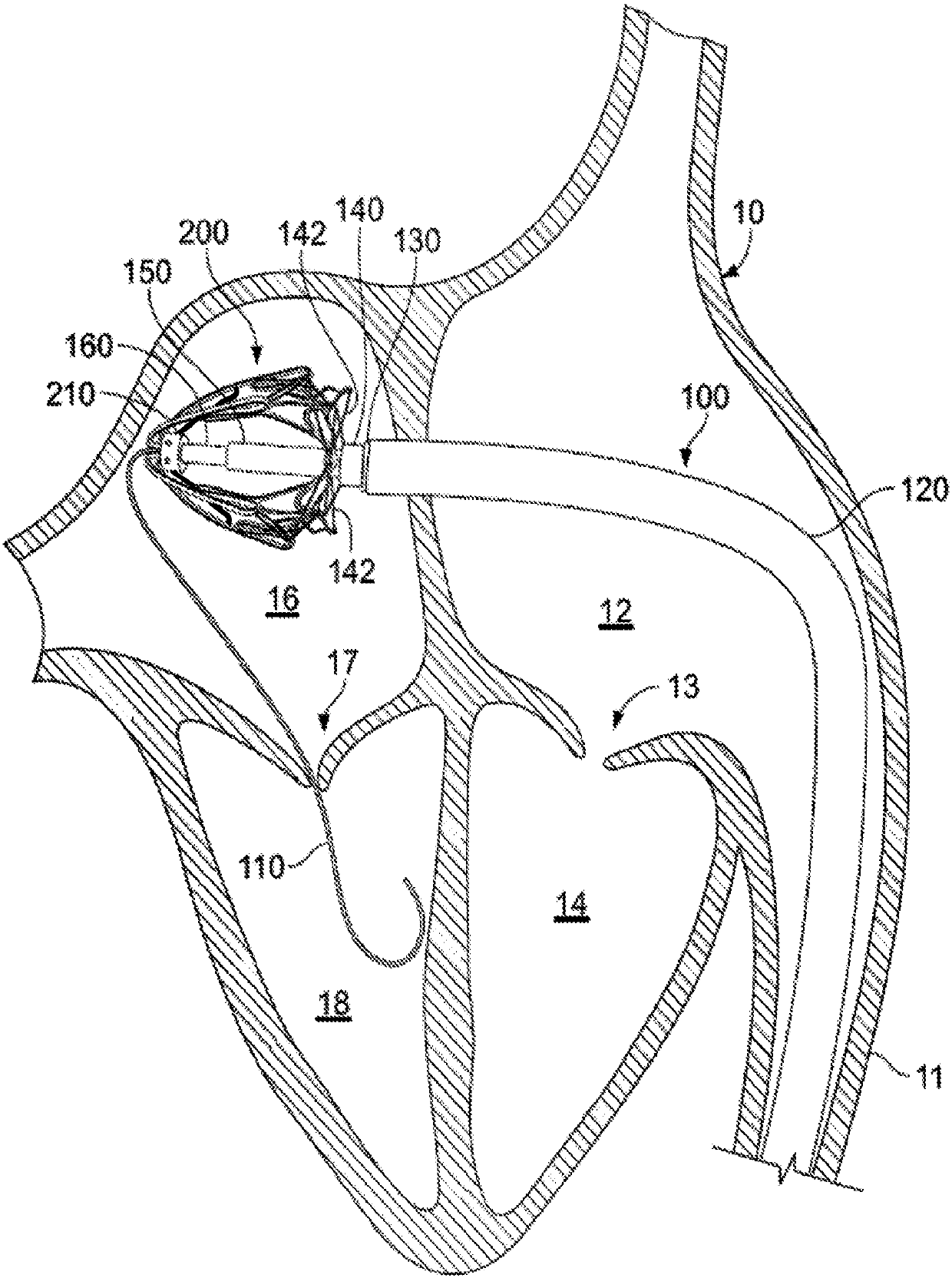
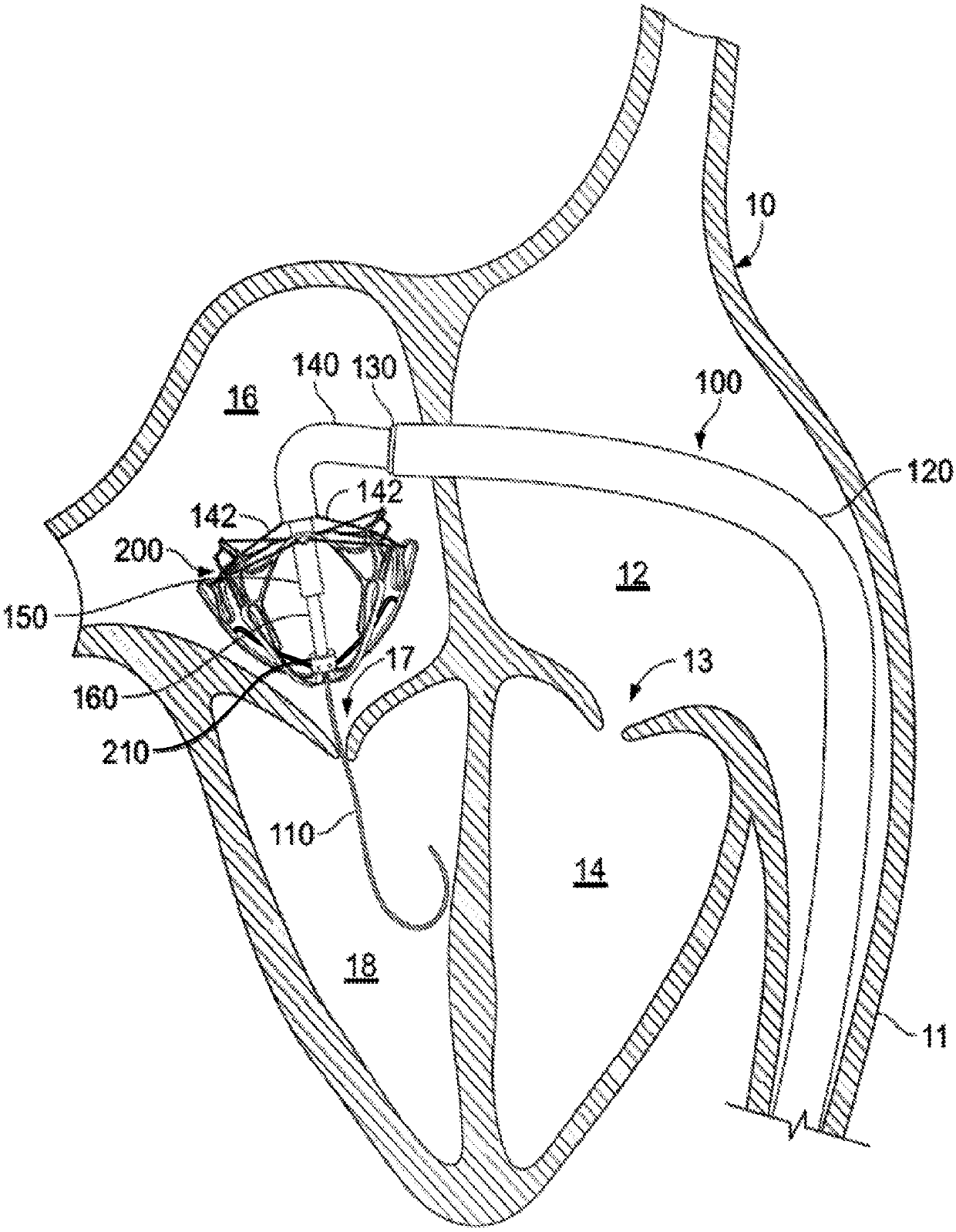
[0063] The present application describes various embodiments of a prosthetic heart valve system, such as a prosthetic mitral valve system, and transcatheter systems and methods for implanting a prosthetic heart valve system. In certain embodiments, the prosthetic mitral valve system can be deployed to interface and anchor cooperatively with the natural anatomy of the mitral valve (and optionally, to allow the chordae of the native mitral valve leaflets to The manner in which the anchoring component continues to function naturally after it has been deployed). As described in more detail below, figure 1 -7 and 15-34 describe transcatheter mitral valve delivery systems and methods whereby a prosthetic mitral valve system can be deployed to coapt and anchor with the anatomy of the native mitral valve. In addition, in Figure 9 -12 and 20-34, various embodiments of a prosthetic mitral valve SAM containment member are described by which the prosthetic valve prevents the native ant...


PUM


Abstract

Prosthetic mitral valves described herein can be deployed using a transcatheter mitral valve delivery system and technique to interface and anchor in cooperation with the anatomical structures of a native mitral valve. This document describes prosthetic heart valve designs and techniques to manage blood flow through the left ventricular outflow tract. For example, this document describes prosthetic heart valve designs and techniques that reduce or prevent obstructions of the left ventricular outflow tract that may otherwise result from systolic anterior motion of an anterior leaflet of the native mitral valve.

Description

[0001] Cross References to Related Applications [0002] This application claims the benefit of US Provisional Application Serial No. 62 / 135,276, filed March 19, 2015. The disclosure of the earlier application is considered part of (and incorporated by reference into) the disclosure of the present application. technical field [0003] This document relates to prosthetic heart valves, such as prosthetic mitral valves, which may be implanted using transcatheter techniques. Background technique [0004] The long-term clinical effects of valvular regurgitation are considered an important cause of cardiovascular-related morbidity and mortality. Thus, for many therapies aimed at treating the mitral valve, a major goal is to significantly reduce or eliminate regurgitation. By eliminating regurgitation at the mitral valve, the damaging effects of volume overload on the left ventricle can be attenuated. Volume overload in mitral regurgitation (MR) involves excess kinetic energy re...

Claims


Application Information

Patent Timeline
Patent Type & Authority Applications(China)
IPC IPC(8): A61F2/24A61F2/82A61F2/86
CPCA61F2/2418A61F2/2439A61F2250/006A61F2/2409A61F2/2436
Inventor K·加内桑R·T·文卡塔苏布磊曼聂C·J·小施魏希T·J·莫笛尔
Owner CAISSON INT LLC
Why Eureka
Try Eureka