
Horizontal type self-cleaning pressure-bearing solid-phase reaction kettle

A solid-phase reaction and self-cleaning technology, applied in chemical/physical/physicochemical fixed reactors, cleaning methods and tools, cleaning methods using tools, etc., can solve problems affecting heat transfer efficiency and easy adhesion of materials , to achieve the effects of improving heat exchange efficiency, increasing output, and improving heat transfer efficiency

Pending Publication Date: 2018-01-23
青岛量子元基环保科技有限公司
View PDF11 Cites 2 Cited by
  • Summary
  • Abstract
  • Description
  • Claims
  • Application Information

AI Technical Summary

Problems solved by technology

[0004] The invention proposes a horizontal self-cleaning pressure-bearing solid-phase reactor, which solves the problem in the prior art that materials are easy to adhere and affect heat transfer efficiency

Method used


Image

  • Horizontal type self-cleaning pressure-bearing solid-phase reaction kettle
  • Horizontal type self-cleaning pressure-bearing solid-phase reaction kettle
  • Horizontal type self-cleaning pressure-bearing solid-phase reaction kettle

Examples


Embodiment 1

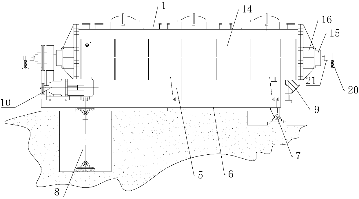
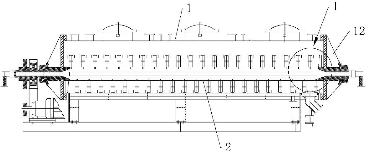
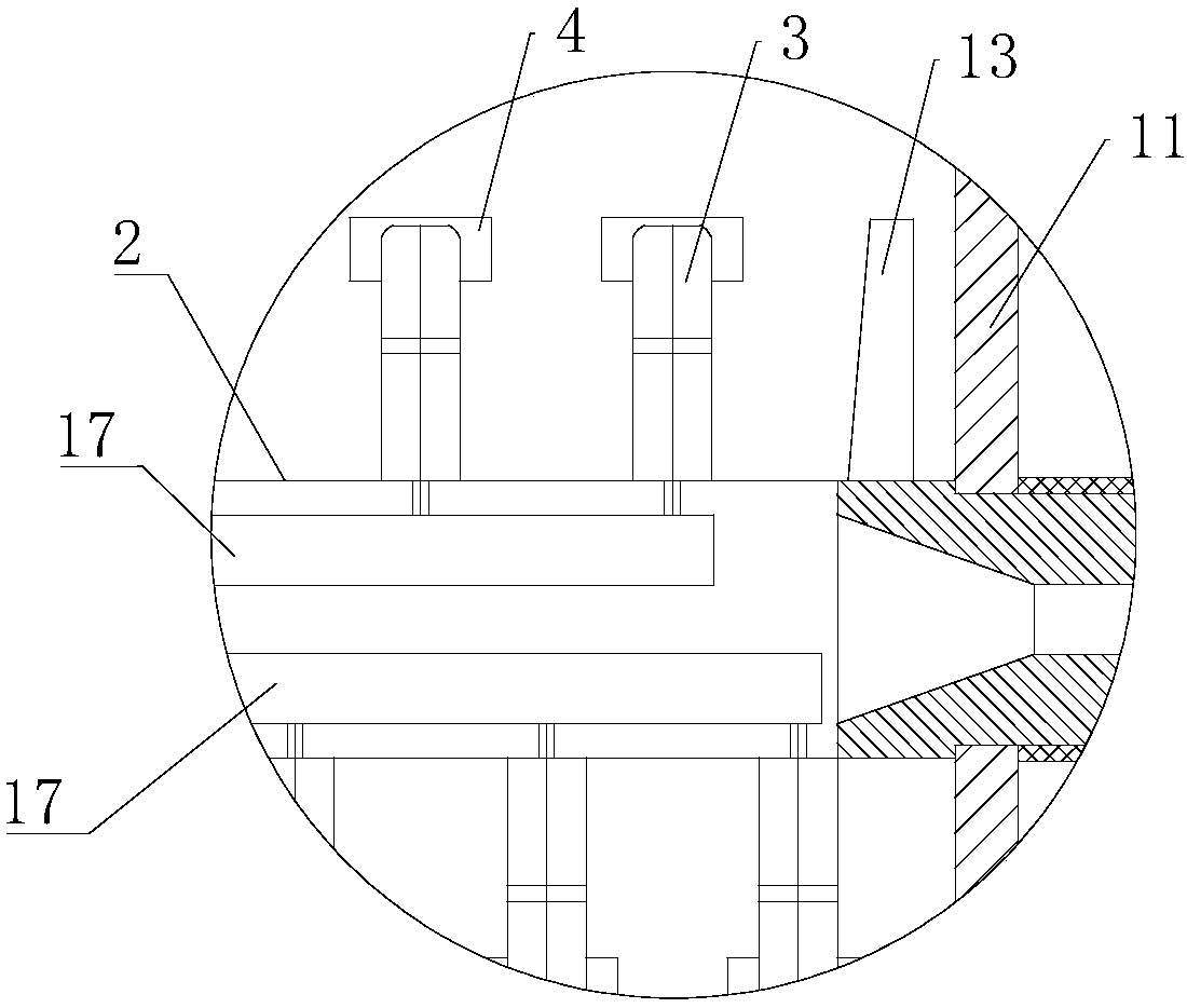
[0049] Such as figure 1 , figure 2 and image 3 As shown, it is an embodiment of the horizontal self-cleaning pressurized solid-phase reactor of the present invention, which includes a horizontally placed reactor cylinder 1, and at least two cylinders along its length are arranged in the reactor cylinder 1. A rotatable stirring shaft 2 extending in a direction, on which two rows of stirring blades 3 arranged symmetrically in the circumferential direction are fixed, the stirring blades 3 are fan-shaped, and the fan-shaped stirring blades 3 The plane where it is located is perpendicular to the stirring shaft 2. With this structure, the axial driving force of the side of the stirring blade 3 on the material is relatively weak. Therefore, after the material enters the reactor cylinder 1, it is mainly dispersed by gravity, and then it is stirred. Under the action of the shaft 2 and the stirring blade 3, it mainly moves radially and circumferentially. In this way, the material wi...

Embodiment 2

[0061] Such as Figure 6 As shown, it is a schematic cross-sectional view of Embodiment 2. The difference between this embodiment and Embodiment 1 is that the reactor cylinder 1 of this embodiment adopts a rectangular structure, and the number of stirring shafts inside it is 4, and the stirring shaft 2. The structure of the upper stirring paddles 3 is the same as that of the first embodiment, and they are all arranged at intervals. In this embodiment, corresponding parts need to be provided on the inner bottom surface of the reactor cylinder 1 to form an ω-shape matching the outer edge of the stirring paddle 3. At this time, the reactor cylinder 1 and the ω-shape have no overlap.

Embodiment 3

[0063] Such as Figure 7 As shown, it is a cross-sectional schematic diagram of Embodiment 3. The difference between this embodiment and Embodiment 1 is that the reactor cylinder 1 of this embodiment adopts an oblong structure, and the number of stirring shafts inside it is 4, and The structure of the stirring paddle 3 on the stirring shaft 2 and Figure 4 Similarly, it is a completely symmetrical structure, and the reactor cylinder 1 and the omega shape of this embodiment are also partially overlapping structures.

[0064] Moreover, in this embodiment, the stirring shaft 2 is arranged at the middle position in the vertical direction of the reactor cylinder body 1, and the gap between the upper edge of the stirring blade 3 and the top surface of the reactor cylinder body 1 is less than 5 cm.


PUM


Abstract

The invention provides a horizontal type self-cleaning pressure-bearing solid-phase reaction kettle, aiming at solving the problems in the prior art that the heat transferring area is small and materials are easily stuck so as to influence the heat transferring efficiency. The reaction kettle comprises a reaction kettle barrel body which is horizontally arranged; the reaction kettle barrel body isinternally provided with at least two stirring shafts which extend along the length direction and are rotatable; two rows of stirring paddles, which are symmetrically distributed in the peripheral direction, on the stirring shafts; the stirring paddles are vector-shaped; the plane of the vector-shaped stirring paddles is vertical to the stirring shaft; an overlapping part formed between the stirring paddles of the adjacent stirring shafts in the axial direction. The horizontal type self-cleaning pressure-bearing solid-phase reaction kettle provided by the invention is convenient to use and has a certain self-cleaning function; caking, shaft covering and wall sticking phenomena of materials can be avoided; the horizontal type self-cleaning pressure-bearing solid-phase reaction kettle has high heat transferring efficiency and has very good practicability.

Description

technical field [0001] The invention relates to the technical field of horizontal reactors, in particular to a horizontal self-cleaning pressure-bearing solid phase reactor with simple structure. Background technique [0002] A solid phase reaction refers to a chemical reaction involving the participation of solid phase substances. For single solid phase, solid-solid phase, and liquid-solid phase reactions dominated by solid phases, the reactants are generally powdery and have poor fluidity. This reaction has the characteristics of slow diffusion, slow reaction, reaction only at the interface, and reaction at high temperature, and in most cases, pressure is required. After the reaction is completed, the reaction product often needs to be further dried. [0003] Reactors suitable for the above characteristics are usually tank reactors. The vertically stirred vertical reactor cannot bear the load of stirring and accumulating powdery materials, and is not suitable for the ab...

Claims


Application Information

Patent Timeline
IPC IPC(8): B01J19/18B08B1/04
Inventor 张云波姜向东
Owner 青岛量子元基环保科技有限公司
Learn More