Power battery explosion-proof valve welding assembly and welding method

A technology for welding components and power batteries, applied in welding equipment, laser welding equipment, metal processing equipment, etc., can solve the problems of uneven shielding gas flow and pressure distribution, rough weld surface, low production yield, etc., to achieve protection The air flow and pressure are uniform, the weld surface is smooth and smooth, and the welding speed is fast.

Active Publication Date: 2019-06-14
深圳市大族锂电智能装备有限公司
View PDF6 Cites 3 Cited by
  • Summary
  • Abstract
  • Description
  • Claims
  • Application Information

AI Technical Summary

Problems solved by technology

However, due to the use of an open side-blowing blowing device, the protective gas flow and pressure distribution are uneven, and the weld surface obtained is rough and uneven, and the production yield is not high.

Method used


Image

  • Power battery explosion-proof valve welding assembly and welding method
  • Power battery explosion-proof valve welding assembly and welding method
  • Power battery explosion-proof valve welding assembly and welding method

Examples


Embodiment 1

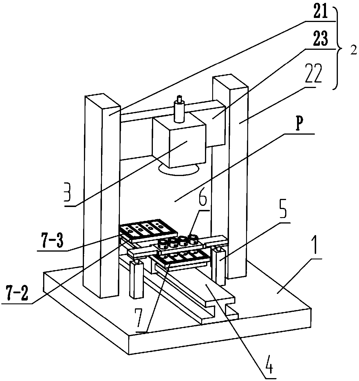
[0047] Such as figure 1 As shown, the power battery explosion-proof valve welding assembly of the present invention includes:

[0048] Platform 1, which can be made of hard materials such as marble, and its shape can be a cuboid structure of 1000*1000*100mm;

[0049] The gantry 2 is fixed on the upper surface of the platform 1; in this embodiment, the gantry 2 specifically includes: a first column 21, a second column 22, and a bridge connecting the first column 21 and the second column 22 The beam 23, the first column 21, the second column 22 and the beam 23 enclose a movable space P that can pass through; the beam 23 can move up and down, and its height is adjustable. In this embodiment, the distance between the bottom of the beam 23 The height of the upper surface of the platform 1 is 400-1000mm (preferably 800mm);

[0050] The galvanometer welding assembly 3 is connected to the gantry 2, more specifically, the galvanometer welding assembly 3 is connected to the middle of ...

Embodiment 2

[0067] This embodiment provides a method for welding an explosion-proof valve of a power battery, which includes the following steps:

[0068] S1. Set up the gantry and the moving assembly on the platform, install the galvanometer welding assembly on the beam of the gantry, and install the blowing device above the moving assembly; and perform pre-spot welding before welding, and at the same time Set the energy gradual and gradual out waveform;

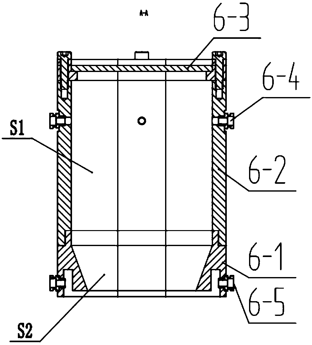
[0069] S2. Transport the tray to the bottom of the air blowing device through the moving assembly, adjust the height of the air blowing device, make the lower end surface of the lower part of the air blowing device fit the power battery cover, and make the The explosion-proof valve of the power battery to be welded is located in the second hollow part of the lower part of the blowing device;

[0070] S3. Input the protective gas through the protective gas intake component of the blowing device, and simultaneously extract the protectiv...


PUM

PropertyMeasurementUnit
heightaaaaaaaaaa
diameteraaaaaaaaaa

Abstract

The invention discloses a power battery anti-explosion valve welding assembly. The power battery anti-explosion valve welding assembly comprises a platform, a portal frame fixed to the upper surface of the platform, a galvanometer welding assembly connected to the portal frame, and at least one blowing device, wherein each blowing device is used for forming a sealed blowing environment for containing a power battery anti-explosion valve to be welded, and the welding laser generated by the galvanometer welding assembly penetrates the blowing devices to weld the power battery anti-explosion valves to be welded in the sealed blowing environments to a power battery cover plate. The power battery anti-explosion valve welding assembly is high in welding speed, the flow and the pressure of protection gas are uniform, the purity of the protection gas is high, the welding seam surface is flat and smooth, and the consistency of the fusion depth and the fusion width is high.

Description

technical field [0001] The invention relates to the field of laser welding, in particular to a power battery explosion-proof valve welding assembly and a welding method. Background technique [0002] Power batteries refer to batteries that provide power sources for equipment such as pure electric vehicles, plug-in hybrid vehicles and electric bicycles. At present, most power batteries are lithium batteries packaged in aluminum shells. The explosion-proof valve is a thin-walled valve body on the battery sealing plate. When the internal pressure of the battery exceeds the specified value, the explosion-proof valve body ruptures to prevent the battery from bursting. Generally, the explosion-proof valve is two aluminum metal sheets with a certain shape connected by laser welding. When the internal pressure rises to a certain value, the aluminum sheet breaks from the designed groove position. In order to prevent the battery from further expanding and causing an explosion, this...

Claims


Application Information

Patent Timeline
Patent Type & Authority Patents(China)
IPC IPC(8): B23K26/21B23K26/14B23K26/10
Inventor 刘继国刘昊胡勇李博雷鹏飞徐作斌高云峰
Owner 深圳市大族锂电智能装备有限公司
Why Eureka
Try Eureka