Apparatus and Method for Filtering Fluids

a filter fluid and apparatus technology, applied in the field of filter fluid apparatus, can solve the problems of low efficiency of uremic solute removal, inability to adequately remove toxins of current diffusion-based therapies, undesirable loss of macromolecules, etc., and achieve the effect of increasing the effective membrane surface area available for mass exchange, facilitating perfusing the area, and uniform blood flow

Inactive Publication Date: 2008-02-14
HUANG ZHONGPING +2
View PDF48 Cites 18 Cited by
  • Summary
  • Abstract
  • Description
  • Claims
  • Application Information

AI Technical Summary

Benefits of technology

[0036] Yet another advantage of the invention is that a nano-porous ceramic tube is more rigid than a hollow fiber. This enables an optimum packing density of the one or more nano-porous ceramic tubes (within the filter module body) to be obtained without requiring crimping, which is currently utilized in known hollow fiber hemodialyzers. Additionally, an optimal packing density enables the dialysate solution to more easily perfuse the areas between the one or more nano-porous ceramic tubes, thus increasing the effective membrane surface area available for mass exchange.
[0037] An additional advantage of utilizing nano-porous ceramic tubes rather than polymer hollow fibers is the realization of a more uniform blood flow. The flow rate of blood in a hollow fiber depends on the fourth power of its radius. As such, even a small change in the radius of a fiber may cause a significant impact on the flow rate of blood in the hollow fiber. Unlike the polymer membrane fibers, there is almost no changing of ceramic membrane tube diameter during the assembly. A more uniform blood flow may therefore be realized.
[0038] The use of nano-porous ceramic tubes also enables the overall size of the filter module to be smaller than that of current hemodialyzers. The increased surface area of a nano-porous ceramic tube, for example, enables more blood to come in contact with pores in the ceramic tube, than with a sheet. Additionally, the tight distribution of the pore size of a nano-porous ceramic tube enables the same surface area to be more efficient in the removal of uremic toxins. Moreover, since the surface area of nano-porous ceramic tube is greater, fewer tubes may be necessary to produce the same effect. Therefore, the overall size of the filter module may be decreased, which is, in general, an important step toward making dialysis therapy a more “portable” therapy.
[0039] Still yet another advantage of the use of nano-porous ceramic tubes for enhanced hemodialysis performance is that the filter module may enjoy an increased longevity over currently-used hemodialyzers. In particular, nano-porous ceramic tubes exhibit greater chemical and thermal resistance than do current dialyzer membranes. This enables the use of high temperature disinfection / sterilization techniques not currently utilized for known dialyzer membranes. The overall resilience of the nano-porous ceramic tubes enables reuse over a greater period of time, which may aid significantly in reducing the cost of an average hemodialysis session.
[0040] According to one implementation, the filter module may further comprise one or more barriers located within the interior volume. The barriers may be configured to force dialysate solution to flow around more of the nano-porous ceramic tubes, both in the core region and the peripheral region of the interior volume. In addition, the barriers may create turbulent flow within the interior volume of the filter module. This may enable more dialysate solution to come in contact with each of the nano-porous ceramic tubes, thus increasing the dialysate-side mass transfer coefficient by reducing the boundary layer.
[0041] Cryoprotectant Removal (or Separation).

Problems solved by technology

Hemodialysis, a medical procedure that uses a machine (e.g., a dialyzer) to filter waste products from the bloodstream and restore the blood's normal components, is often a necessary and inconvenient form of treatment for those patients with end-stage renal disease or other kidney disorders.
Studies also suggest that current diffusion-based therapies may be limited in their ability to adequately remove toxins.
The non-uniformity of pore size and pore distribution of current hemodialysis membranes tends to result in the low efficiency of uremic solute removal, as well as the undesirable loss of macromolecules such as albumin (an important blood component) during hemodialysis.
Despite an improved efficiency in selective solute removal, the basic morphology of the membrane remains sponge-like and therefore has a non-uniform pore structure and size.
In addition to the known deficiencies of existing hemodialysis membranes, additional drawbacks exist with regard to the configuration of known dialyzer modules (or housings).
The non-optimized fiber packing density common in current dialyzers often results in the channeling of dialysate at standard flow rates.
These represent yet additional drawbacks of known dialyzers.
As is the case for non-optimized packing density, this reduces the effective membrane surface area available for mass exchange.
Current dialyzers are often reused due to their high cost.
The repeat disinfection of dialysis membranes, however, tends to negatively impact dialysis performance.
In particular, chemical disinfectants may alter membrane material.
Moreover, the low temperature resistance of most known membranes makes the use of high temperature disinfection / sterilization reprocessing methods almost impossible.
The relatively long dialysis therapy time and high dialysis session frequency limits the social activities and mobility of dialysis patients.
These and other drawbacks exist with known hemodialysis membranes, dialyzer configurations, and dialysis therapy.
Additionally, one or more of the aforementioned drawbacks may also be encountered when hollow fiber filters are utilized in other applications including, for example, cryopreservation, the separation of blood components (e.g., plasmapheresis), and controlling the concentration of cells in a biological fluid solution.
One drawback of using a centrifuge to separate blood plasma from the remainder of its blood components is that the mechanical forces may damage the blood cells.

Method used


Image

  • Apparatus and Method for Filtering Fluids
  • Apparatus and Method for Filtering Fluids
  • Apparatus and Method for Filtering Fluids

Examples


Embodiment Construction

[0073] Described herein is a filter module utilizing a nano-porous ceramic membrane that may be adapted for use in various applications including, but not limited to, enhanced hemodialysis performance, the removal (or separation) of cryoprotectant from biological materials, the separation of blood components, and controlling the concentration of cells in a biological fluid solution.

[0074] Filter Module.

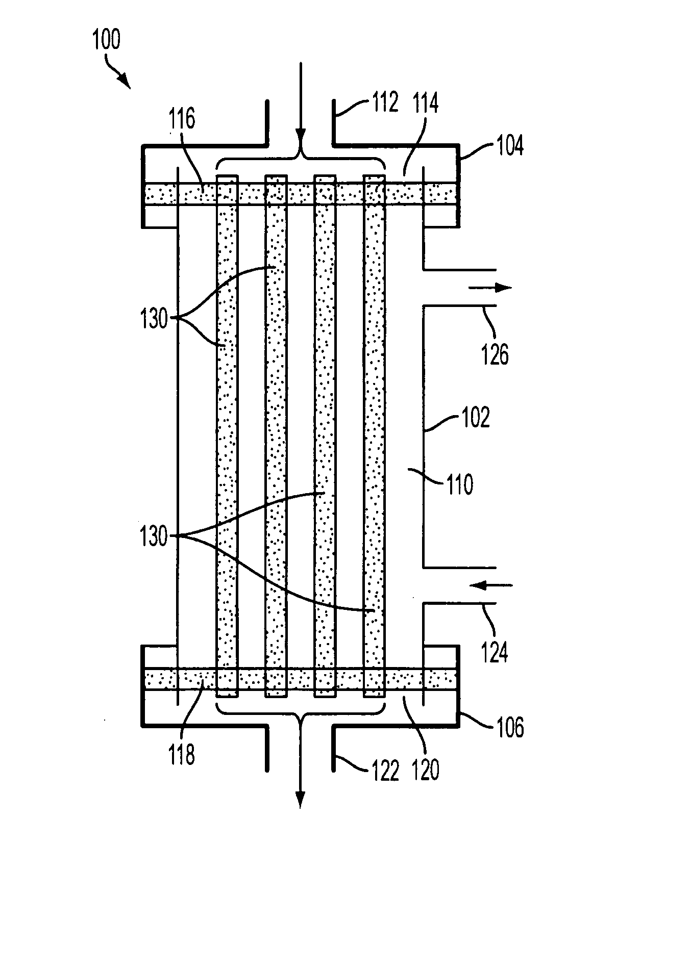
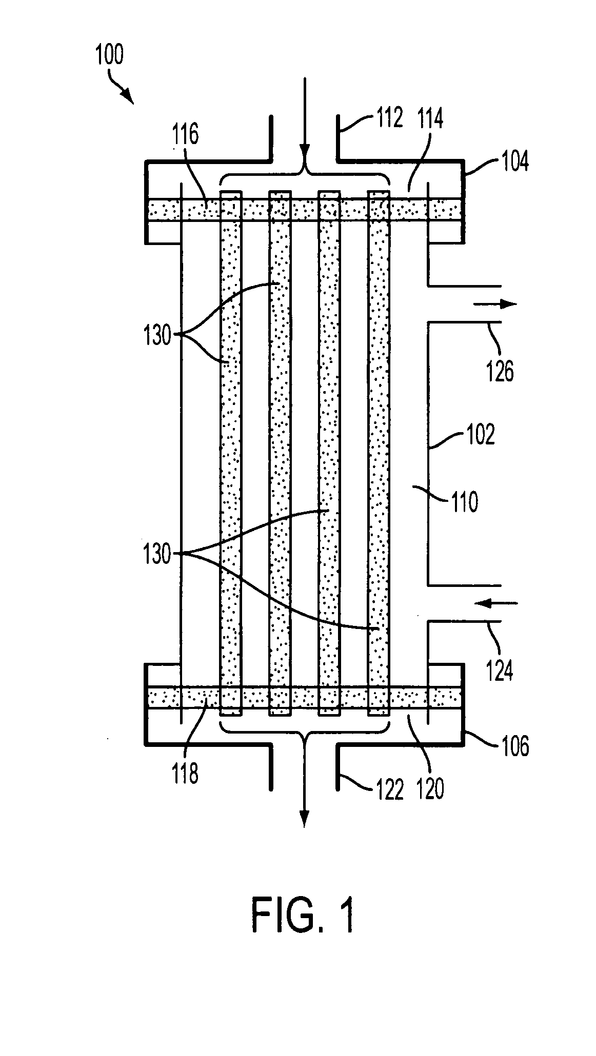
[0075]FIG. 1 is an exemplary illustration of a filter module 100, according to an aspect of the invention. In one implementation, filter module 100 may comprise a housing that includes an inlet cap 104, module body 102, and outlet cap 106. Inlet cap 104 and outlet cap 106 may be integral with, or removable from, module body 102 as known and understood by those having skill in the art. Inlet cap 104, module body 102, and outlet cap 106 may each be formed from a rigid plastic material, or from other materials commonly used to fabricate similar devices. In some implementations, inlet c...


PUM


Abstract

A filter module utilizing a nano-porous ceramic membrane is provided for various applications including, but not limited to, enhanced hemodialysis performance, the removal (or separation) of cryoprotectant from biological materials, the separation of blood components (e.g., plasmapheresis), and controlling the concentration of cells in a biological fluid solution.

Description

CROSS-REFERENCE TO RELATED APPLICATIONS [0001] This application is a continuation-in-part of U.S. patent application Ser. No. 11 / 540,705, filed Oct. 2, 2006, entitled “Apparatus and Method for Enhanced Hemodialysis Performance,” which claims priority to U.S. Provisional Patent Application Ser. No. 60 / 722,404, filed Oct. 3, 2005, each of which are incorporated herein by reference in their entirety.STATEMENT REGARDING FEDERALLY SPONSORED RESEARCH OR DEVELOPMENT [0002] This invention was made with U.S. Government support under Contract No. 1 R41 DK074254-01, awarded by The National Institutes of Health. The U.S. Government has certain rights in this invention.FIELD OF THE INVENTION [0003] The invention relates generally to methods and apparatus for filtering fluids, and more particularly to a filter module utilizing a nano-porous ceramic membrane for various applications including, but not limited to, enhanced hemodialysis performance, the removal (or separation) of cryoprotectant from...

Claims


Application Information

Patent Timeline
Patent Type & Authority Applications(United States)
IPC IPC(8): B01D61/14
CPCA61M1/16B01D63/02B01D63/021B01D63/06B01D2323/08B01D67/0065B01D71/024B01D2313/08B01D2313/086B01D63/061
Inventor HUANG, ZHONGPINGVAN GEERTRUYDEN, WILLIAM HERMANGAO, DAYONG
Owner HUANG ZHONGPING
Why Eureka
Try Eureka