Liquid phase flow battery pile of Fe/Cr system

A fluid battery, liquid phase technology, applied in fuel cells, fuel cell components, circuits, etc., can solve the problems of large current loss, incomplete utilization of carbon felt area, limited current sharing effect, etc., to improve current efficiency , Improve the effect of electrolyte flow

Inactive Publication Date: 2014-12-03
SUZHOU JIURUN ENERGY TECH
View PDF9 Cites 17 Cited by
  • Summary
  • Abstract
  • Description
  • Claims
  • Application Information

AI Technical Summary

Problems solved by technology

None of the flow channels in these patents can realize the uniform flow of the electrolyte in the electrode, which often causes problems such as incomplete utilization of the carbon felt area and large pressure difference of the single cell in the stack.
Patent CN201220672976.X "A Liquid Flow Frame Device

Method used


Image

  • Liquid phase flow battery pile of Fe/Cr system
  • Liquid phase flow battery pile of Fe/Cr system
  • Liquid phase flow battery pile of Fe/Cr system

Examples


Embodiment 1

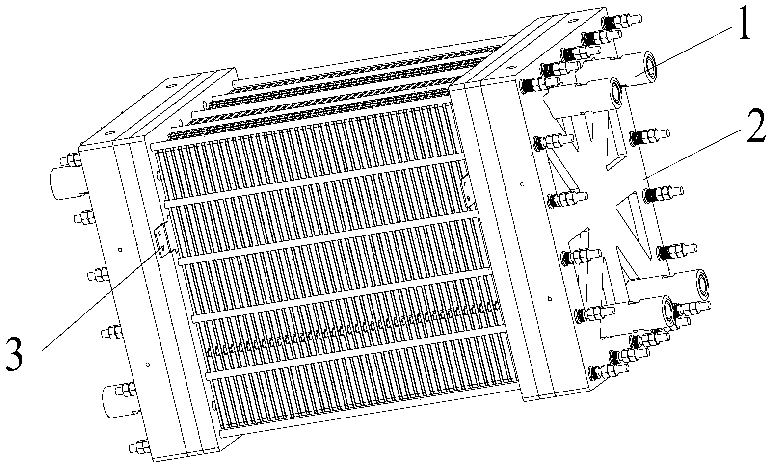
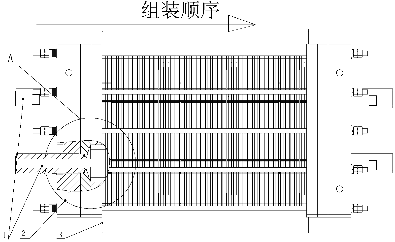
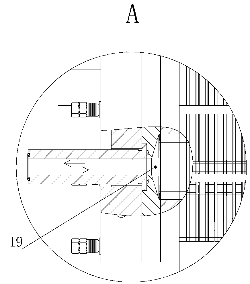
[0037] An Fe / Cr system liquid-phase flow battery stack is composed of 40 single cells connected in series, and each single cell includes a positive electrode and a negative electrode, a diaphragm, a positive electrode electrolyte and a negative electrode electrolyte, and the iron-chromium redox flow battery is respectively Fe in different valence states 2+ / Fe 3+ , Cr 2+ / Cr 3+ As the redox of the positive and negative poles of the battery, the positive and negative electrolytes are stored in two liquid storage tanks respectively, and the active electrolyte is driven by an acid-resistant liquid pump to the reaction site (battery stack) and then returned to the liquid storage tank to form a cycle. Liquid flow circuit to realize the charging and discharging process. Both sides of the cell stack are clamped by end plates 1, and there are cell stack interfaces 1 on the end plates, which are positive electrolyte inlet, negative electrolyte inlet, positive electrolyte outlet, and...

experiment example 1

[0052] Experimental example 1: Runner structure test

[0053] A single cell was assembled from battery components of the same size as in Example 1, and the end plates were made of transparent plastic for easy observation. The flow channel on the plate frame includes a shared channel, two parallel serpentine flow channels, an equalizing groove, a flow equalizing bell mouth and a flow equalizing groove, but there is no equalizing island in the middle of the equalizing groove. The circulation pump is used to drive the electrolyte to enter the single cell through the shared channel, and enter the serpentine flow channel through the flow channel inside the plate. The terminal of the serpentine flow channel is divided into 4 bell mouths, so the flow of electrolysis into the bell mouth is uneven. Causes uneven distribution of electrolyte on the carbon felt (electrode).

Embodiment 2

[0055] An Fe / Cr system liquid-phase flow battery stack is composed of 50 single cells connected in series, and each single cell includes a positive electrode and a negative electrode, a diaphragm, a positive electrode electrolyte and a negative electrode electrolyte, and the iron-chromium redox flow battery is respectively Fe in different valence states 2+ / Fe 3+ , Cr 2+ / Cr 3+ As the positive and negative poles of the battery redox. The stack structure is the same as in Example 1.

[0056] Positive plate frame size: length 650mm, width 460mm, thickness 11mm.

[0057] Negative plate frame size: length 650mm, width 460mm, thickness 7mm.

[0058] Diaphragm size: length 390mm, width 435mm.

[0059] Carbon felt size: length 360mm, width 223mm, thickness 7.5mm. Cover area is 122cm 2 .

[0060] The shared passage takes the form of an "O" ring seal. The diaphragms are sealed on both sides and positioned relative to each other. The bipolar plates are wrapped and sealed. Ot...


PUM


Abstract

The invention provides a liquid flow frame of a Fe/Cr flow battery and an electric pile consisting of the liquid flow frame. A runner for flowing of an electrolyte is formed in the liquid flow frame and comprises a sharing channel, two snakelike runners, uniform-distributing tanks, horn mouths and uniform-flowing tanks, wherein the electrolyte flows into single batteries through the sharing channel and flows into the snakelike runners through runners in a pole plate, multiple horn mouths are formed in the tail end of each snakelike runner, and all the horn mouths are communicated to the uniform-flowing tanks. A battery pile is formed by multiple single batteries through series connection, wherein each single battery comprises a positive electrode, a negative electrode, a diaphragm, a positive electrode electrolyte and a negative electrode electrolyte, the positive electrode consists of a bipolar plate and a carbon felt and is arranged in the liquid flow frame, and four sides, opposite to the liquid flow frame, of the bipolar plate are surrounded by a package type sealing structure.

Description

technical field [0001] The invention belongs to the field of batteries, and in particular relates to a liquid-phase fluid battery stack. Background technique [0002] The liquid flow battery is a new type of battery, which is a high-performance battery that uses the positive and negative electrolytes to separate and circulate separately. It has the characteristics of high capacity, wide application field (environment), and long cycle life. Redox flow battery is a new type of large-capacity electrochemical energy storage device that is being actively developed. It is different from batteries that usually use solid material electrodes or gas electrodes. Its active substance is a flowing electrolyte solution. Its most notable features are In the case of large-scale power storage, under the situation of widespread use of renewable energy, it is foreseeable that flow batteries will usher in a period of rapid development. The iron-chromium redox flow battery is a kind of redox f...

Claims


Application Information

Patent Timeline
IPC IPC(8): H01M8/02H01M8/0258
CPCH01M8/0263H01M8/0265H01M8/0273H01M8/0276H01M8/188Y02E60/50
Inventor 马志啟韩志洁温志建肖冬王瑞宾
Owner SUZHOU JIURUN ENERGY TECH
Why Eureka
Try Eureka