Crankshaft and main shaft neck grinding method

A technology of main journal and crankshaft, which is applied in the grinding field of main journal of crankshaft, can solve the problems of machining fine grinding difference, etc., and achieve the effect of improving service life, high machining accuracy and improving machining accuracy

Inactive Publication Date: 2018-01-23
卢丽
View PDF6 Cites 2 Cited by
  • Summary
  • Abstract
  • Description
  • Claims
  • Application Information

AI Technical Summary

Problems solved by technology

[0003] The technical problem to be solved by the present invention is to provide a grinding method of the crankshaft main journal to solve the problem of poor precision grinding of the existing crankshaft main journal coaxiality

Method used


Image

  • Crankshaft and main shaft neck grinding method

Examples


Embodiment 1

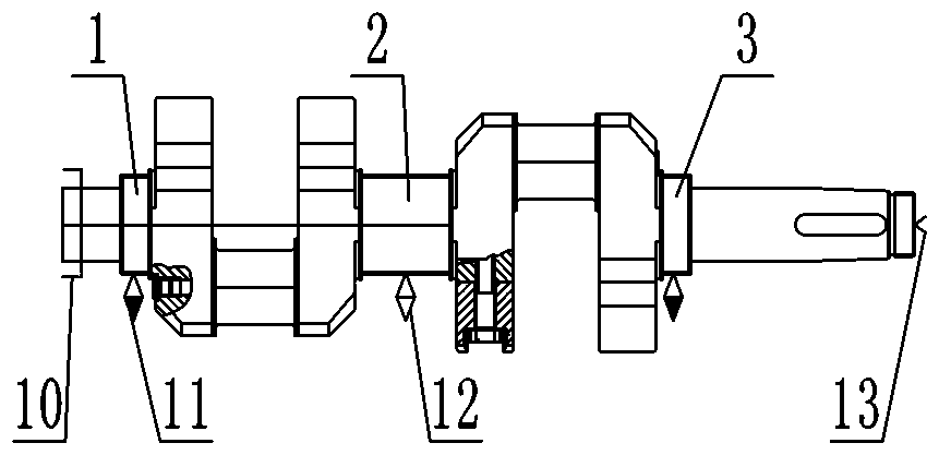
[0018] A crankshaft is provided with an intermediate main journal 2 and bearing position main journals respectively located on both sides of the intermediate main journal 2, and the two bearing position main journals are bearing position main journal 1 and bearing position main journal 3 respectively;

[0019] The grinding method of this crankshaft main journal comprises the steps:

[0020] A. Grind the top holes at both ends of the crankshaft first;

[0021] B. The main shaft of the machine tool is flexibly connected to one end of the crankshaft through a universal joint 10, and the tip hole at the other end of the crankshaft abuts against the tip 13 of the tailstock of the machine tool;

[0022] C. Set the middle main journal 2 as the reference support position, adjust the circle, and loosen the top 13 of the tailstock after adjustment;

[0023] D. First use the grinding wheel to roughly grind the middle main journal 2, and at the same time adjust the auxiliary bracket 11 a...

Embodiment 2

[0027] A crankshaft is provided with an intermediate main journal 2 and bearing position main journals respectively located on both sides of the intermediate main journal 2, and the two bearing position main journals are bearing position main journal 1 and bearing position main journal 3 respectively;

[0028] The grinding method of this crankshaft main journal comprises the steps:

[0029] A. Grind the top holes at both ends of the crankshaft first;

[0030] B. The main shaft of the machine tool is flexibly connected to one end of the crankshaft through a universal joint 10, and the tip hole at the other end of the crankshaft abuts against the tip 13 of the tailstock of the machine tool;

[0031] C. Set the middle main journal 2 as the reference support position, adjust the circle, and loosen the top 13 of the tailstock after adjustment;

[0032] D. First use the grinding wheel to roughly grind the middle main journal 2, and at the same time adjust the auxiliary bracket 11 a...


PUM


Abstract

The invention discloses a crankshaft and main shaft neck grinding method. The method comprises the following steps: (A) firstly, a tip hole is grinded; (B) a main shaft of a machine tool is flexibly connected with a crankshaft through a universal coupling; and the other end of the crankshaft butts against the tip of a tail frame of the machine tool; (C) a middle main shaft neck is used as a reference support position; and after adjustment, the tail frame is loosened; (D) the middle main shaft neck is roughly grinded by using a grinding wheel, so that a grinding quantity of 0.1-0.12 mm is formed between the size of the middle main shaft neck in the reference support position and the middle main shaft neck of a finished crankshaft; (E) the step (D) is repeated; multiple times of fine grinding are repeated; and the middle main shaft neck is grinded to the size of the middle main shaft neck of the finished crankshaft; and (F) main shaft necks in two bearing positions are grinded to reach the size of the main shaft neck in the bearing position of the finished crankshaft to finish the operation; and when the main shaft necks in the two bearing positions are grinded, a bracket is used onthe middle main shaft neck. Compared with the prior art, the method can solve the problem of weak fine grinding of traditional crankshaft and main shaft neck coaxiality.

Description

technical field [0001] The invention relates to the technical field of mechanical manufacturing, in particular to a grinding method for crankshaft main journals. Background technique [0002] A crankshaft generally has a main journal and a connecting rod journal, and the coaxiality of the main journal is an important index to measure the quality of the crankshaft, which directly affects the performance of the installed machinery. If the coaxiality of the main journal is out of tolerance, the crankshaft will generate additional bending stress during operation, which will aggravate the wear of the journal, and will produce alternating stress of tension and compression at the transition fillet. Under stress, it is easy to produce cracks at the transition fillet, and in severe cases, it will cause the crankshaft to break; and the coaxiality of the crankshaft is formed during the fine grinding of the main journal. The first and foremost problem to be solved. Contents of the in...

Claims


Application Information

Patent Timeline
IPC IPC(8): B24B1/00B24B19/00
Inventor 卢丽
Owner 卢丽
Why Eureka
Try Eureka