Furnace air-distribution structure inhibiting generating of carbon monoxide

A carbon monoxide and furnace technology, applied in the direction of incinerators, combustion methods, combustion types, etc., can solve the problems of reducing waste incineration, reducing boiler load, increasing coal volume, etc., to prolong the residence time, improve the residence time, and ensure full combustion Effect

Pending Publication Date: 2018-01-23
ZHEJIANG WANGNENG ENVIRONMENTAL PROTECTION CO LTD
View PDF0 Cites 2 Cited by
  • Summary
  • Abstract
  • Description
  • Claims
  • Application Information

AI Technical Summary

Problems solved by technology

As long as the circulating fluidized bed waste incinerator cannot solve the problem of uniform feeding, positive pressure, and slight positive pressure, even if the above means and methods are used to g

Method used


Image

  • Furnace air-distribution structure inhibiting generating of carbon monoxide
  • Furnace air-distribution structure inhibiting generating of carbon monoxide
  • Furnace air-distribution structure inhibiting generating of carbon monoxide

Examples


Example Embodiment

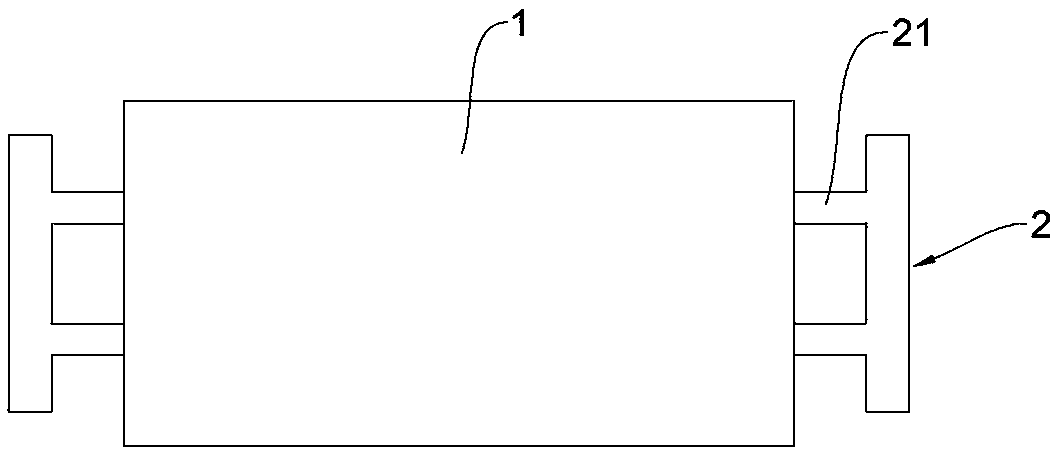
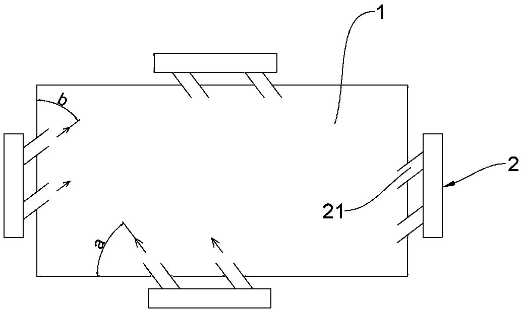
[0027] Example: such as Figure 2 to Figure 4 As shown, a furnace air distribution structure for inhibiting the generation of carbon monoxide includes a furnace 1 and a secondary air device 2 that feeds air into the furnace 1. The secondary air device 2 has at least three layers and is arranged up and down along the height of the furnace. The number of the device 2 is generally three layers, or four layers, and the distance between each layer is 1.2 meters to 1.5 meters. There are at least four sets of secondary air devices 2 in each layer, which are respectively arranged around the hearth, and the hearth 1 has a rectangular structure.

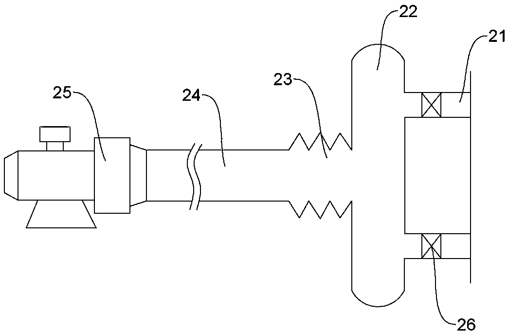
[0028] Such as figure 2 As shown, the secondary air device 2 includes an air inlet pipe connected to the furnace 1, and the air inlet pipes in the secondary air device 2 of each layer are located at the same height. The blowing direction of the air inlet pipe is inclined to the furnace wall of the furnace 1 along the same circumferential direct...


PUM

PropertyMeasurementUnit
Angleaaaaaaaaaa
Lengthaaaaaaaaaa

Abstract

The invention relates to the technical field of fluidized bed waste incinerators, in particular to a furnace air-distribution structure inhibiting generating of carbon monoxide. The furnace air-distribution structure comprises a furnace and secondary air devices for supplying air to the furnace; the at least four groups of secondary air devices are correspondingly arranged around the furnace; eachsecondary air device comprises an air inlet tube which communicates with the furnace; and the air blowing direction of each air inlet tube is inclined to a furnace wall of the furnace in the same circumference direction, so that an annular second air flow is formed in the furnace. According to the furnace air-distribution structure, the secondary air devices are annularly arranged, so that secondary air enters the furnace in the tangential direction, generating of positive pressure and micro positive pressure in the furnace is effectively reduced and inhibited through multilayer relay rotation, an air curtain formed by flue gas making contact with the wall is inhibited, generating of the carbon monoxide is significantly reduced, and requirements of environmental protection emission are met.

Description

technical field [0001] The invention relates to the technical field of fluidized bed garbage incinerators, in particular to a furnace air distribution structure for suppressing the generation of carbon monoxide. Background technique [0002] With the improvement of environmental protection emission requirements, after carbon monoxide is included in the emission control index, the circulating fluidized bed can no longer meet the emission requirements. Every power plant, especially the waste incineration power plant, was constructed and put into operation in accordance with the environmental protection requirements at that time in terms of design and EIA. The current equipment complies with the EIA or environmental protection policies at that time, and carbon monoxide was not included in the environmental protection requirements at that time. Now carbon monoxide is included in environmental protection requirements, that is to say, yesterday's equipment does not match today's r...

Claims


Application Information

Patent Timeline
IPC IPC(8): F23G5/30F23G5/44
Inventor 陈国强
Owner ZHEJIANG WANGNENG ENVIRONMENTAL PROTECTION CO LTD
Why Eureka
Try Eureka