Sewage treatment equipment capable of separating sludge and use method

A kind of sewage treatment equipment and sludge technology, applied in the direction of water/sludge/sewage treatment, water/sewage multi-stage treatment, chemical instruments and methods, etc., can solve the problem of blocked pipes and filter screens, easily damaged cutter heads, and difficult cleaning and other issues, to achieve the effect of energy saving, high degree of automation, and complete functional items

Inactive Publication Date: 2018-01-26
广西南宁桂尔创环保科技有限公司
View PDF7 Cites 4 Cited by
  • Summary
  • Abstract
  • Description
  • Claims
  • Application Information

AI Technical Summary

Problems solved by technology

The current sewage treatment technology is to purify the sewage and discharge it directly after reaching the standard. The sewage discharged by some factories, schools, etc. contains high heat, and the direct discharge produces waste.
In addition, in the traditional sewage treatment process, reamers are often used to crush the silt and sundries. When the garbage in the silt gets stuck on the reamer cutter head, the cutter head is easily damaged.
At the same time, the debris in the sewage sludge is easy to block the pipes and filter screens, making it relatively difficult to clean

Method used


Image

  • Sewage treatment equipment capable of separating sludge and use method
  • Sewage treatment equipment capable of separating sludge and use method
  • Sewage treatment equipment capable of separating sludge and use method

Examples


Embodiment 1

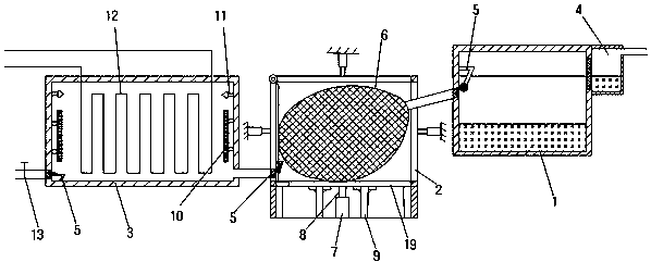
[0029] A sewage treatment equipment capable of separating sludge, including a sedimentation tank 1, a squeezing tank 2, a heat exchange tank 3 and a main control system; the inlet of the sedimentation tank 1 is provided with a primary filter 4, and the outlet is connected to the squeezing tank 2; the squeeze pool 2 is surrounded by six movable plate surfaces, and each surface is provided with a squeeze device 8; a filter bag 6 is arranged in the squeeze pool; the filter bag 6 is placed on the squeeze On the extrusion device 8 on the bottom surface of the pressure pool 2; the outlet of the extrusion pool 2 is connected to the heat exchange pool 3; the inside of the heat exchange pool 3 is provided with a coil pipe 12, and the wall of the pool is provided with an electric heater 10 and a high-pressure water gun 11 , the bottom outlet is provided with a solenoid valve 13; the sedimentation tank 1, extrusion tank 2 and heat exchange tank 3 are all arranged underground; the outlets ...

Embodiment 2

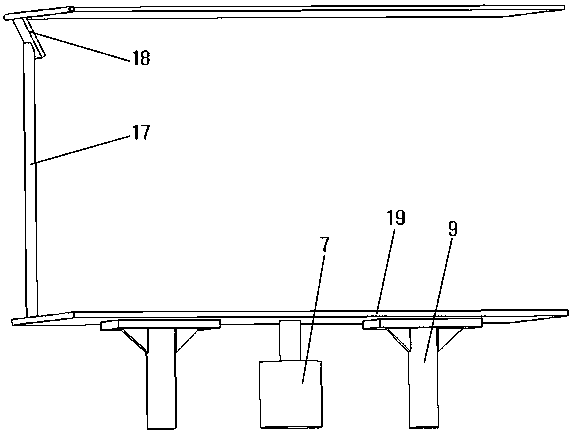
[0033] The second embodiment is basically the same in structure and principle as the first embodiment, except that the bottom of the squeeze pool 2 is provided with a support column 9 . When the filter bag 6 is not filled with sludge, the support column 9 assists the squeezing device 8 at the bottom 2 of the pool to support the filter bag 6 .


PUM


Abstract

The invention provides sewage treatment equipment capable of separating sludge and a use method. The sewage treatment equipment comprises a sedimentation tank, an extrusion tank and a heat exchange tank, wherein a primary filtering tank is arranged at the inlet of the sedimentation tank; the outlet of the sedimentation tank is connected with the extrusion tank; the extrusion tank is formed by sixmovable board surfaces; an extrusion device is arranged on each surface; a filtering bag is arranged in the extrusion tank; the filtering bag is laid on the extrusion of the bottom surface of the extrusion tank 2; the outlet of the extrusion tank is connected with the heat exchange tank; a coil is arranged inside the heat exchange tank; an electric heater and a high-pressure water gun are arrangedon the wall of the heat exchange tank; an electromagnetic valve is arranged at the outlet in the bottom of the heat exchange tank; the sedimentation tank, the extrusion tank and the heat exchange tank are all arranged underground; an automatic cleaner is arranged at each of the outlets of the sedimentation tank, the extrusion tank and the heat exchange tank; a sensor is arranged in each of the sedimentation tank, the extrusion tank and the heat exchange tank and is connected with a main control system. The sewage treatment equipment can recycle and utilize heat while being capable of separating sludge in sewage, and meanwhile extrudes sludge impurities into blocks which are convenient for subsequent processing.

Description

technical field [0001] The invention belongs to the technical field of sewage treatment, and relates to sewage treatment equipment capable of separating sludge and a use method. Background technique [0002] Sewage treatment is the process of purifying sewage to meet the water quality requirements of a certain water body for drainage or reuse. The current sewage treatment technology is to purify the sewage and discharge it directly after reaching the standard. The sewage discharged by some factories and schools contains high heat, and the direct discharge produces waste. In addition, in the traditional sewage treatment process, a reamer is often used to crush the silt and sundries. When the garbage in the silt gets stuck on the reamer cutter head, the cutter head is easily damaged. At the same time, the debris in the sewage sludge can easily block the pipes and filter screens, making it relatively difficult to clean. Contents of the invention [0003] In order to solve t...

Claims


Application Information

Patent Timeline
Patent Type & Authority Applications(China)
IPC IPC(8): C02F9/04
Inventor 戚海冰
Owner 广西南宁桂尔创环保科技有限公司
Why Eureka
Try Eureka