
High-strength cable descending rope connector structure and machining method thereof

A joint structure and high-strength technology, applied in the field of cable drop, can solve the problems of occupying the operating space of cable drop personnel, the influence of cable drop operation, and the impact on service life, etc., and achieve the effect of compact structure, small loss of connection strength, and avoiding life reduction.

Pending Publication Date: 2018-01-26
AEROSPACE LIFE SUPPORT IND LTD
View PDF8 Cites 1 Cited by
  • Summary
  • Abstract
  • Description
  • Claims
  • Application Information

AI Technical Summary

Problems solved by technology

[0003] The current cable drop rope joint structure is generally a braided type, that is, the cable drop rope wraps around the end and reinserts the end of the cable drop rope into the cable drop rope body to form a rope loop that can be used for connection. The strength is high, but the appearance quality is poor, especially the size is very large. For the helicopter with a low door height, its size occupies the operating space of the cable drop personnel, which has an impact on the cable drop operation, and the cable drop rope is directly attached to the metal The structure is easy to cause wear and tear during use, which affects the service life

Method used


Image

  • High-strength cable descending rope connector structure and machining method thereof
  • High-strength cable descending rope connector structure and machining method thereof
  • High-strength cable descending rope connector structure and machining method thereof

Examples


Embodiment Construction

[0024] The present invention will be further described below in conjunction with the drawings and embodiments.

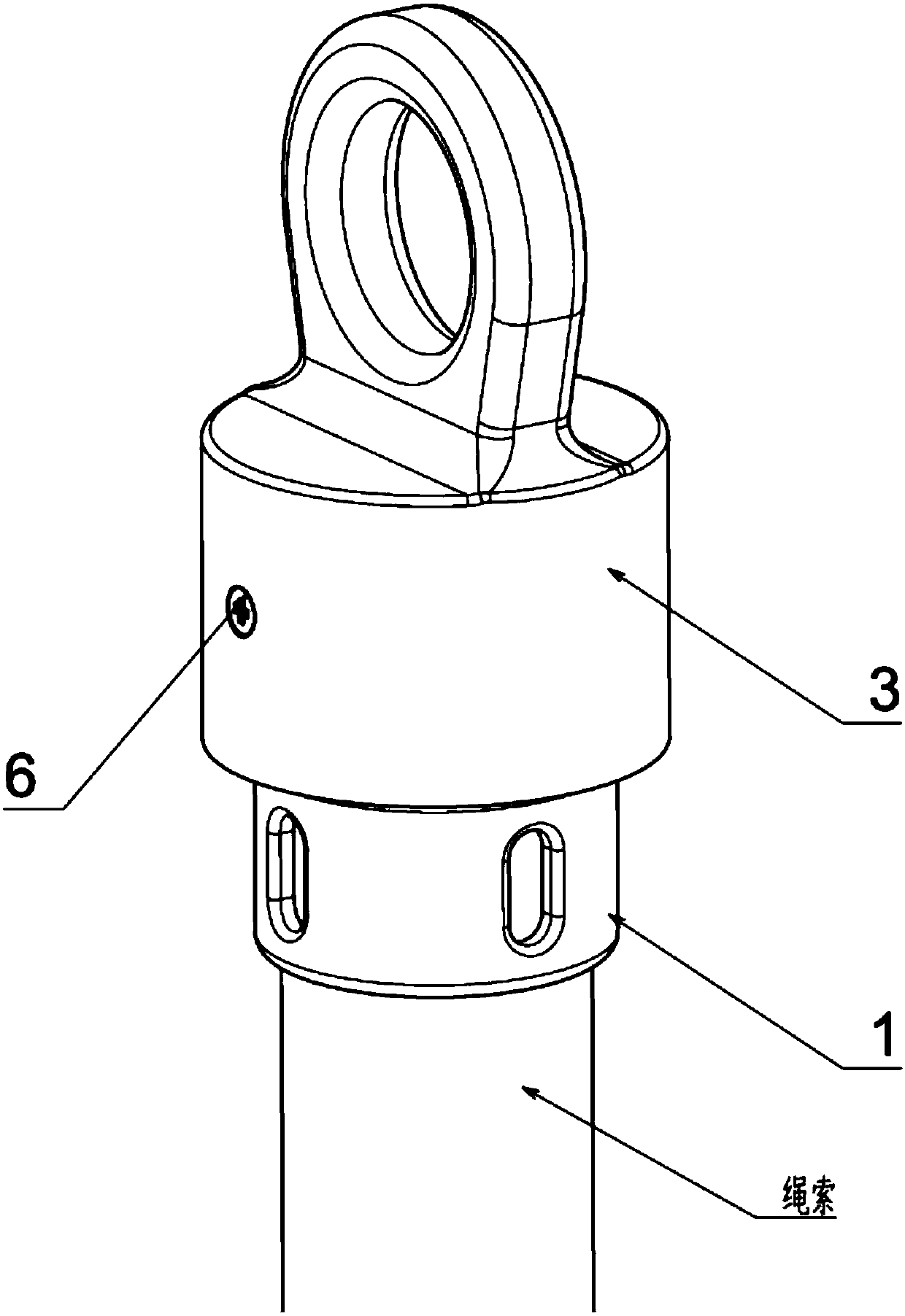
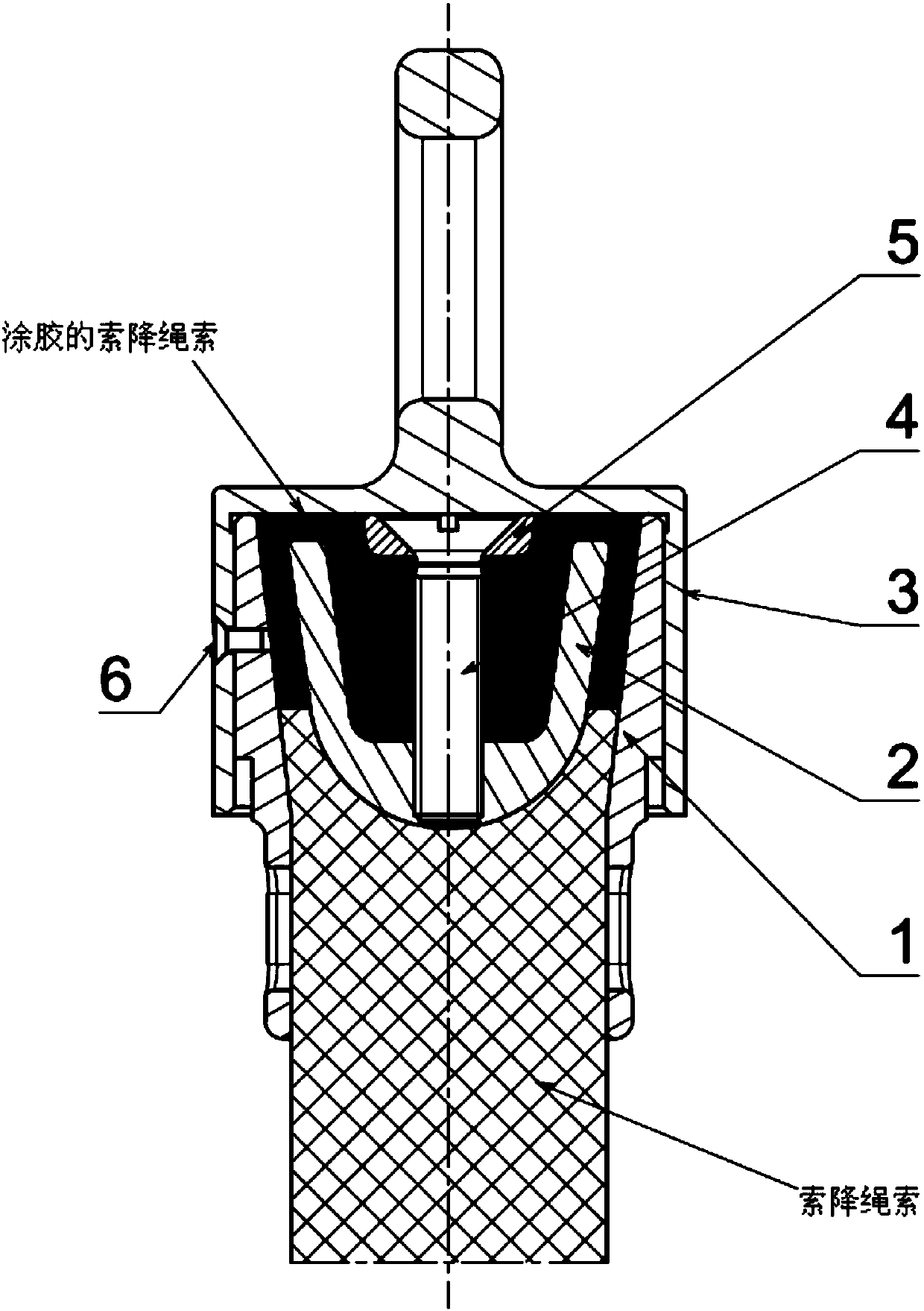
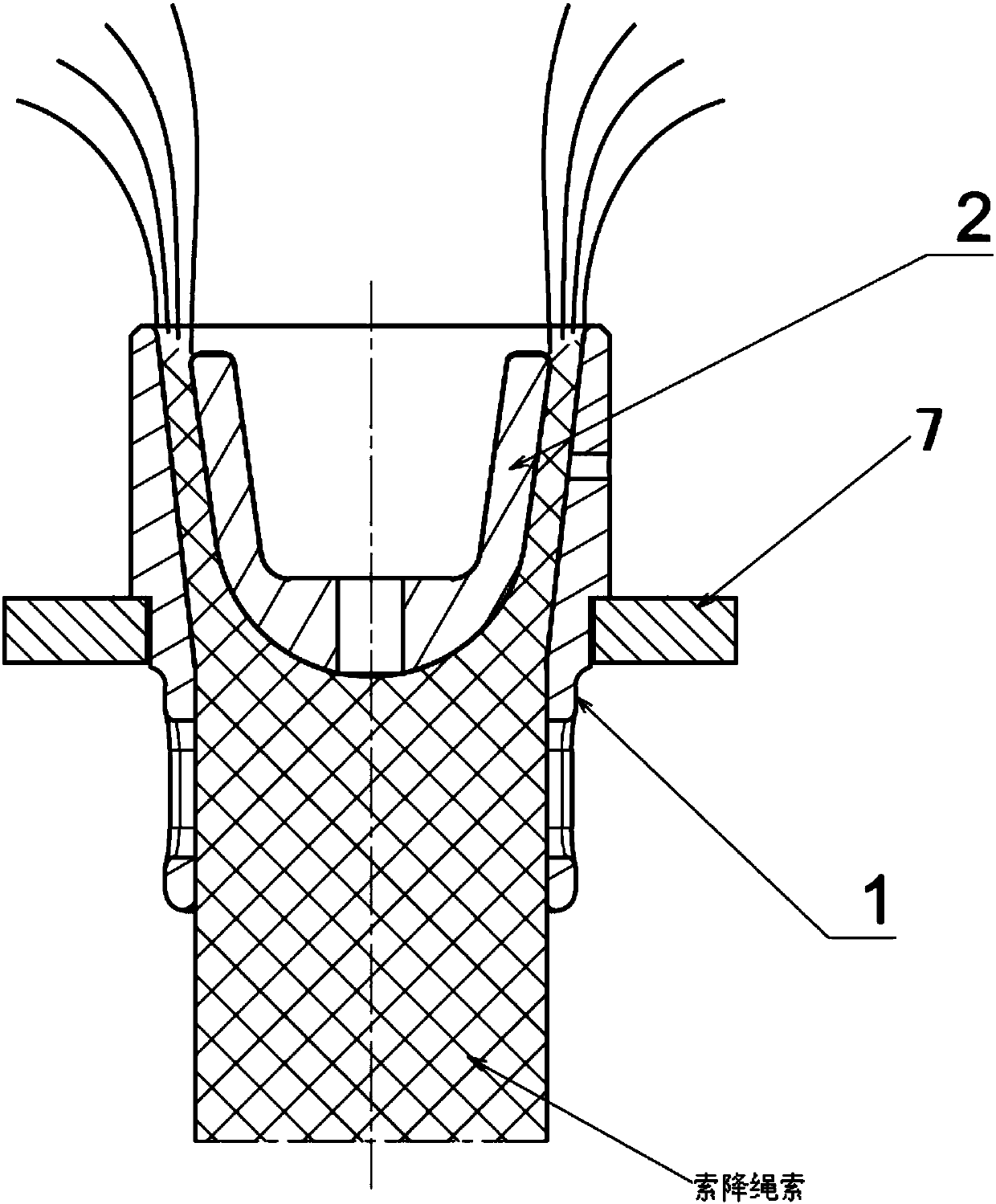
[0025] Such as figure 1 with figure 2 As shown, a high-strength cable-dropping rope joint structure includes an annular cylindrical connecting seat 1, a cable-dropping rope passing through the connecting seat 1 and being scattered at the end, and located in the center of the cable-falling rope breaking up in the connecting seat 1. A wedge with a cavity on the top 2, a pressure plate 5 located above the center of the inner cavity of the connecting seat 1, a screw 4 that passes through the pressure plate 5 and is connected to the wedge 2, and a hanging cover with a ring structure connected to the top of the connecting seat 1 3. The connecting seat 1, the wedge 2, the pressing plate 5 and the hanging cover 3 are all metal parts. The cable drop rope fiber extends from the wedge 2 and the connecting seat 1 and folds back into the cavity, the cavity and the wedge 2 and the c...


PUM


Abstract

The invention relates to a high-strength cable descending rope connector structure and a machining method thereof. The high-strength cable descending rope connector structure comprises an annular barrel-shaped connecting base, a cable descending rope penetrating the connecting base and provided with the scattered end, a wedge located in the center of the scattered position of the cable descendingrope located in the connecting base and provided with the top provided with a containing cavity, a pressing plate located above the center of the containing cavity in the connecting base, a screw penetrating the pressing plate to be connected with the wedge and a hoisting cover connected with the top of the connecting base and provided with an annular structure; the connecting base, the wedge, thepressing plate and the hoisting cover are all metal pieces, cable descending rope fibers extend out from the position between the wedge and the connecting base and are turned back to the containing cavity, and matching parts of the containing cavity and the wedge and connecting base are back taper structures; the overall cable descending rope is compressed and fixed through the wedge and the connecting base, the cable descending rope fibers in the containing cavity are compressed and fixed through the wedge and the pressing plate, and the cable descending rope fibers in the containing cavityand the cable descending rope fibers between the wedge and the connecting base are soaked with glue liquid to be subject to pasting and curing. The connector connecting strength loss is small, the structure is compact, and the service life is high.

Description

Technical field [0001] The invention belongs to the technical field of cable drop, and specifically relates to a high-strength cable drop cable joint structure and a processing method thereof. Background technique [0002] When performing a helicopter rope drop task, the rope drop rope needs to be suspended and installed on the helicopter through the joint structure at the end to establish a person rope drop channel. Therefore, the connection strength and reliability of the rope drop rope joint structure are related to the safety of the rope drop personnel. [0003] The current cable drop rope joint structure is generally braided, that is, the cable drop rope wraps around the end and re-weaves the cable drop rope end into the cable drop rope body to form a rope loop that can be used for connection. High strength, but poor appearance quality, especially large size. For helicopters with low door height, its size occupies the operating space of cable drop personnel and affects cable d...

Claims


Application Information

Patent Timeline
Patent Type & Authority Applications(China)
IPC IPC(8): F16G11/05F16G11/04
Inventor 李琦张琦张鹍钱叶辉周清艳马启明陈庆龙朱运林
Owner AEROSPACE LIFE SUPPORT IND LTD
Learn More