An intelligent optical fiber fusion splicer based on the Internet of Things
What is Al technical title?
Al technical title is built by PatSnap Al team. It summarizes the technical point description of the patent document.
A technology of intelligent optical fiber and fusion splicer, which is applied in the field of optical fiber equipment, can solve problems such as dust, lower quality of optical fiber communication, and inability to adjust the strength of the clamping mechanism to clamp the optical fiber, so as to achieve the effect of improving quality
Active Publication Date: 2020-08-07
杭州东南吉通网络有限公司
View PDF13 Cites 0 Cited by
Summary
Abstract
Description
Claims
Application Information
AI Technical Summary
This helps you quickly interpret patents by identifying the three key elements:
Problems solved by technology
Method used
Benefits of technology
Problems solved by technology
[0003] In general fiber optic fusion splicers, it is impossible to adjust the strength of the clamping mechanism to clamp the optical fiber. If the clamping force is too large, the optical fiber will be bent, which will cause the optical fibers at both ends to be unable to be completely aligned during the fusion splicing process, and reduce the communication of the optical fiber after splicing. Quality, not only that, in the general fusion splicing process, the optical fiber is first cleaned and then put into the fusion splicer. During the process of putting the optical fiber into the fusion splicer, the surface of the optical fiber may be stained with dust again, resulting in a decrease in the light guide rate of the optical fiber after fusion splicing
Method used
Image
Click on the blue label to locate the original text in one second.
Reading with bidirectional positioning of images and text.
Examples
Embodiment Construction
[0029] The present invention will now be described in further detail with reference to the drawings. These drawings are all simplified schematic diagrams, which merely illustrate the basic structure of the present invention in a schematic manner, so they only show the structures related to the present invention.
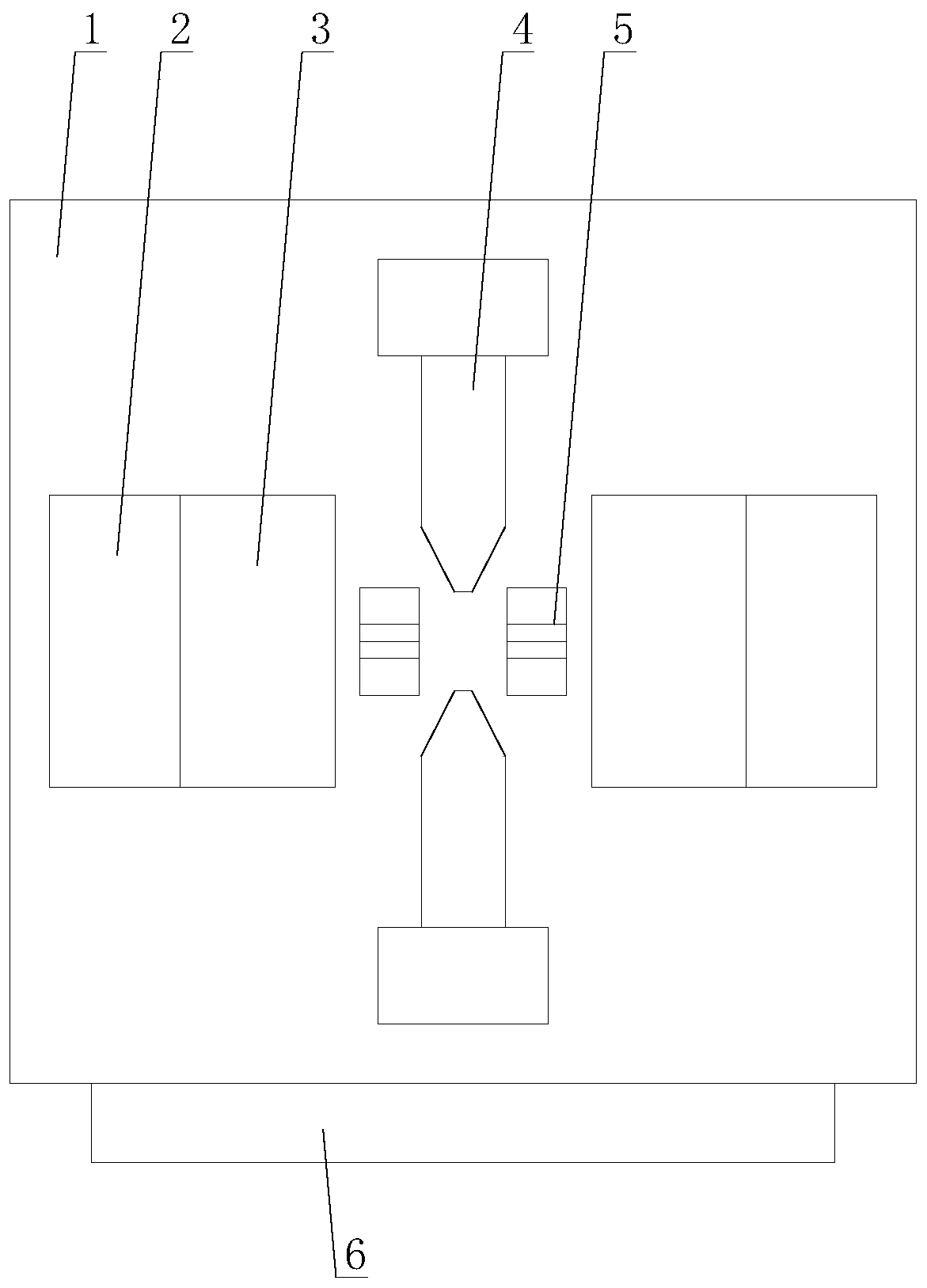
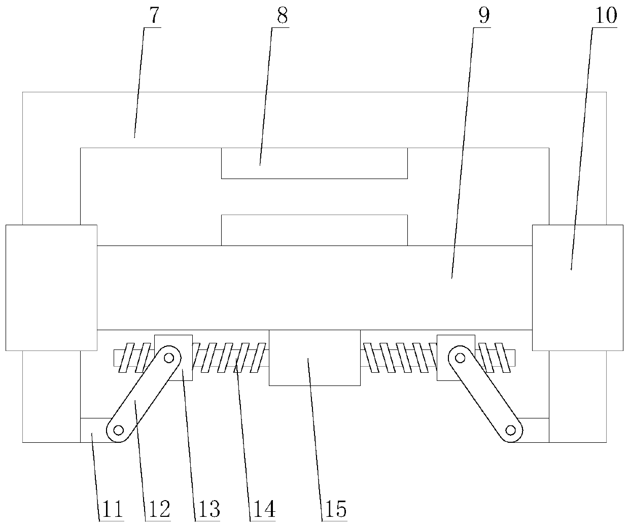
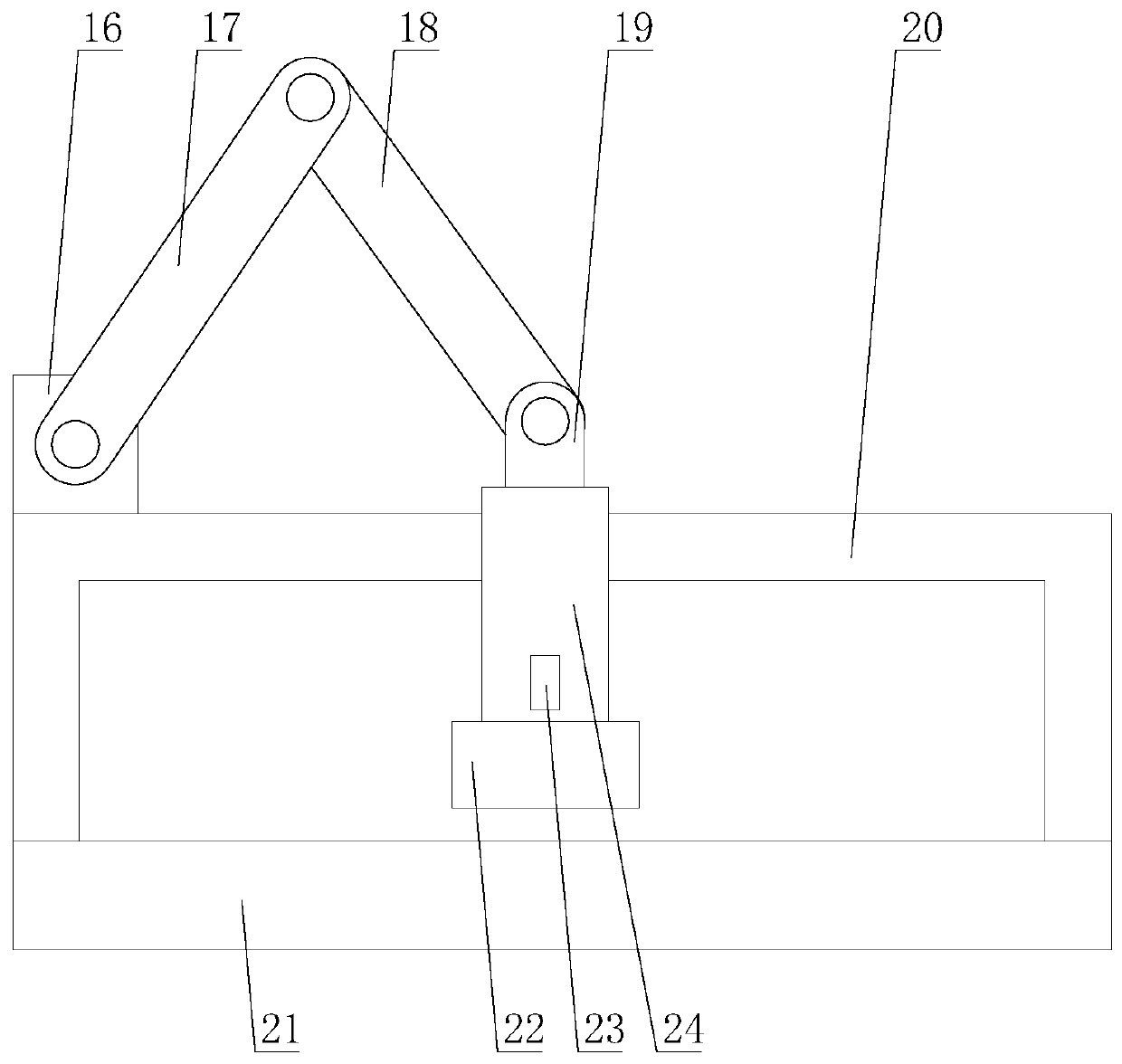
[0030] Such as Figure 1-Figure 5 As shown, an intelligent optical fiber fusion splicer based on the Internet of Things includes a body 1, a control panel 6, a central control mechanism, two wiping mechanisms 2, two clamping mechanisms 3, two electrodes 4 and two V-shaped grooves 5. The control panel 6 is arranged under the body 1, the two electrodes 4 are both arranged on the body 1, the two V-shaped grooves 5 are arranged in the middle of the two electrodes 4, and the two The clamping mechanism 3 is respectively arranged on one side of the two electrodes 4, the two wiping mechanisms 2 are respectively arranged on one side of the two clamping mechanisms 3, and the wip...
PUM
Abstract
The present invention relates to an intelligent fiber fusion splicer based on internet of things. The intelligent fiber fusion splicer comprises a machine body, a control panel, a central control mechanism, a wiping mechanism, a clamping mechanism, an electrode and a V-shaped groove. The clamping mechanism comprises an elevating rack, a supporting rod, a fixing block and a driving assembly, the driving assembly comprises a first motor, a screw, a first moving block, a second transmission rod and a first transmission rod, and the wiping mechanism comprises a second motor, a third transmission rod, a fourth transmission rod, a fifth transmission rod, a supporting rack, a tray, a cleaning block and a second moving block. According to the intelligent fiber fusion splicer based on the internetof things, the clamping mechanism can adjust the strength for clamping the fibers real-timely, so that during the fiber clamping process, the situations that the fibers bend due to the excessive strength, and cannot be clamped due to the insufficient strength, are avoided, and the fiber splicing quality is improved. The wiping mechanism wipes the surfaces of the fibers after the fibers are put inthe fiber fusion splicer, so that the surfaces of the fibers are clean, and the fiber splicing quality is improved.
Description
Technical field [0001] The invention relates to the field of optical fiber equipment, in particular to an intelligent optical fiber fusion splicer based on the Internet of Things. Background technique [0002] Optical fiber fusion splicer is mainly used for the construction and maintenance of optical cables in optical communication, so it is also called optical cable fusion splicer. The general working principle is to use high-voltage arc to melt the sections of two optical fibers and use a high-precision motion mechanism to gently advance the two optical fibers into one , In order to realize the coupling of the fiber mode field. [0003] In general optical fiber fusion splicers, it is impossible to adjust the clamping force of the clamping mechanism on the optical fiber. If the clamping force is too large, the optical fiber will be bent, which will lead to the incomplete alignment of the two optical fibers during the fusion splicing process, which reduces the communication of the ...
Claims
Application Information
Patent Timeline
Application Date:The date an application was filed.
Publication Date:The date a patent or application was officially published.
First Publication Date:The earliest publication date of a patent with the same application number.
Issue Date:Publication date of the patent grant document.
PCT Entry Date:The Entry date of PCT National Phase.
Estimated Expiry Date:The statutory expiry date of a patent right according to the Patent Law, and it is the longest term of protection that the patent right can achieve without the termination of the patent right due to other reasons(Term extension factor has been taken into account ).
Invalid Date:Actual expiry date is based on effective date or publication date of legal transaction data of invalid patent.