Radio-frequency front-end circuit and communication device

A front-end circuit and high-frequency technology, which is applied in the field of high-frequency front-end circuits and communication devices, and can solve problems such as optimization of filter characteristics and complexity of filter design.

Active Publication Date: 2018-01-26
MURATA MFG CO LTD
View PDF5 Cites 14 Cited by
  • Summary
  • Abstract
  • Description
  • Claims
  • Application Information

AI Technical Summary

Problems solved by technology

[0006] However, if the number of combinations of frequency bands for CA operation increases, and there are many such combinations, it is necessary to adjust the impedance of each filter for each combination of frequency bands, so that the design of each filter is complicated, and it is difficult

Method used


Image

  • Radio-frequency front-end circuit and communication device
  • Radio-frequency front-end circuit and communication device
  • Radio-frequency front-end circuit and communication device

Examples


Embodiment approach 1

[0109] [1.1 Structure of high-frequency front-end circuit]

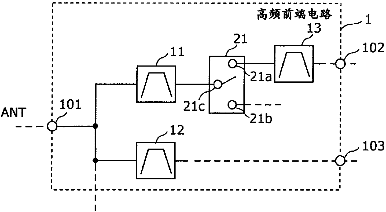
[0110] Figure 1A It is a circuit configuration diagram of the high-frequency front-end circuit 1 of the first embodiment. As shown in the figure, the high-frequency front-end circuit 1 includes a first filter 11 , a second filter 12 , a third filter 13 , a switch 21 , an antenna common terminal 101 , and input and output terminals 102 and 103 . The high-frequency front-end circuit 1 is a complex elastic wave filter device including a first filter 11 and a second filter 12 connected in common through an antenna common terminal 101 .

[0111] The common terminal 101 can be connected to, for example, an antenna element, and the input / output terminals 102 and 103 can be connected to a high-frequency signal processing circuit via an amplifier circuit.

[0112] The first filter 11 is a filter having a first terminal and a second terminal, the first terminal is connected to the antenna common terminal 101 , and has a fir...

Embodiment approach 2

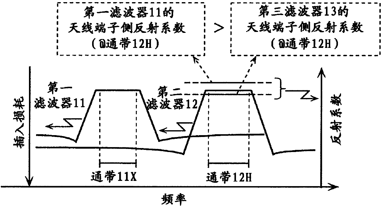
[0201] In Embodiment 1, it is preferable to use a structure in which the first filter 11 and the second filter 12 are shared and connected through the antenna common terminal, and the first filter 11 and the third filter 13 are connected in series via a switch. The reflection coefficient is increased in the first filter 11 which has a large influence on the reflection characteristics, and the filter characteristics such as pass characteristics, attenuation characteristics, temperature characteristics, and bandwidth are ensured in the third filter 13 which has a small influence on the reflection characteristics. illustrate. In this embodiment, the combination of the structures of the 1st filter 11 and the 3rd filter 13 is illustrated from the viewpoint mentioned above.

[0202] In this embodiment, the first filter 11 and the third filter 13 are formed of elastic wave resonators, but may have a ladder-type filter structure. In this case, the one or more elastic wave resonators ...

Embodiment approach 3

[0283] In the present embodiment, the reduction in loss and miniaturization of a high-frequency front-end circuit composed of a demultiplexer circuit connected to a common terminal of the antenna and filters corresponding to each frequency band arranged in the rear stage of the demultiplexer circuit is achieved. The structure is explained.

[0284] Figure 13A It is a circuit configuration diagram of the high-frequency front-end circuit 6 of the third embodiment. The high-frequency front-end circuit 6 shown in the figure includes an antenna common terminal 101, an LB filter 11L, an MB filter 11M, an HB filter 11H, a filter 13b for B3, a filter 13f for B30, and LNAs 31, 32, and 34.

[0285] LB filter 11L, MB filter 11M, and HB filter 11H are demultiplexing circuits connected to antenna elements.

[0286] The LB filter 11L is a low-frequency region pass-side filter with a low-frequency range (for example, 2 GHz or less) as a passband.

[0287] The HB filter 11H is a high-freq...


PUM

PropertyMeasurementUnit
Thicknessaaaaaaaaaa

Abstract

The invention provides a small-size radio-frequency front-end circuit, by which a signal transmission character of low loss is maintained even CA motion is carried out. A radio-frequency front-end circuit (1) includes a first filter (11) that has a first pass band and is connected to an antenna common terminal (101), a second filter (12) that has a second pass band and is connected to the antennacommon terminal (101), a switch (21) that includes a common terminal (21c) and selection terminals (21a and 21b), the common terminal being connected to the first filter, and a third filter (13) thatis connected to one of the selection terminals and is disposed between the switch and an input/output terminal (102). A reflection coefficient of the first filter alone in the second pass band viewedfrom the antenna common terminal is larger than a reflection coefficient of the third filter alone in the second pass band viewed from the antenna common terminal.

Description

technical field [0001] The invention relates to a high-frequency front-end circuit and a communication device. Background technique [0002] For mobile phones in recent years, it is desired to use one terminal to support multiple frequencies and wireless methods (multi-band and multi-mode). In order to cope with multi-band and multi-mode front-end modules, it is necessary to perform high-speed processing of multiple transmission and reception signals without degrading the quality. In particular, carrier aggregation is sought to simultaneously transmit and receive high-frequency signals in multiple frequency bands. [0003] In Patent Document 1, an RF system including a LB (low band) diversity antenna, an MB (mid band) / HB (high band) diversity antenna, and a diversity module is disclosed (refer to Patent Document 1 Image 6 ). The diversity module has a single-pole multi-throw switch connected to the MB / HB diversity antenna, a plurality of filters connected to the single-po...

Claims


Application Information

Patent Timeline
IPC IPC(8): H04B1/401H04B1/00
Inventor 竹内壮央宫崎大辅奥田哲朗
Owner MURATA MFG CO LTD
Why Eureka
Try Eureka