Portable heat preservation box

An incubator and portable technology, which is applied in the direction of insulated containers, lighting and heating equipment, containers, etc., can solve the problems of load waste, achieve the effects of preventing interference, reducing space occupation, and facilitating transportation and recycling

Inactive Publication Date: 2018-01-30
FUJIAN SUPERTECH ADVANCED MATERIAL
View PDF7 Cites 6 Cited by
  • Summary
  • Abstract
  • Description
  • Claims
  • Application Information

AI Technical Summary

Problems solved by technology

[0002] At present, the incubators on the market are all one-piece incubators with a box-type structure, and the shape and volume do not change when used and recycled. The market urgently needs an incubator that is easy to use, carry and recycle, and has a variable volume to solve the incubator transportation process. The trouble caused by the waste of the load is convenient for recycling and reuse

Method used


Image

  • Portable heat preservation box
  • Portable heat preservation box
  • Portable heat preservation box

Examples


Embodiment 1

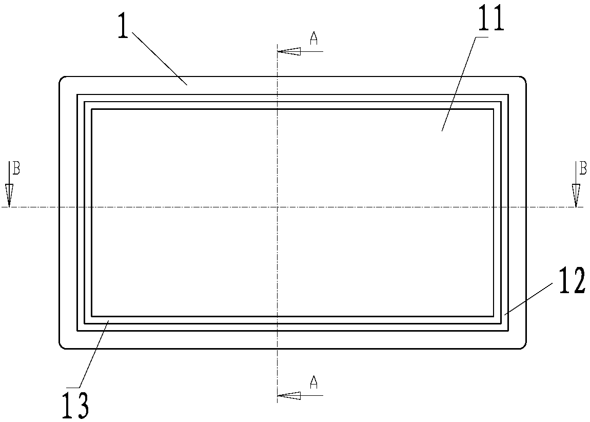
[0039] refer to Figure 1-11 , a detachable portable heat preservation box, comprising: an upper cover, a lower cover 1, front and rear side panels 2 and left and right side panels 3;

[0040] A first boss 11 protrudes outward from the opposite sides of the upper cover plate and the lower cover plate 1 , and a second boss 12 protrudes outward from the outer side of the first boss 11 ; the first boss A back-shaped groove 13 is formed between 11 and the second boss 12 .

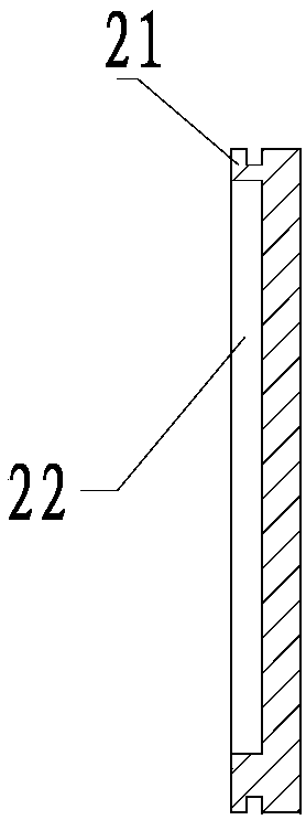
[0041] A third boss 21 protrudes outward from the opposite side of the front and rear side plates 2, and a part of the surface of the third boss 21 is concave inward to form a groove 22 toward the square away from the heat preservation accommodating cavity; the The upper and lower ends of the third boss are the same height as the front and rear side plates 2 , and the thickness thereof is equal to or slightly larger than the groove width of the return-shaped groove 13 , so as to form a static fit with the retu...

Embodiment 2

[0051] The difference between this embodiment and Embodiment 1 is that in this embodiment, the upper cover, the lower cover, the front and rear side panels, and the left and right side panels are adhered by adhesives to form a non-removable incubator, although the disassembly is sacrificed. However, the sealing and thermal insulation performance of the incubator has been further improved.

Embodiment 3

[0053] refer to Figure 12 , the difference between the present embodiment and the embodiment 1 is: in the present embodiment, the front and back of the upper cover plate, the lower cover plate 1 and the front and rear side plates 2, the left and right side plates 3 are also respectively provided with a panel 4; the described The panel 4 is one of plastic parts, kraft paper, aluminum foil, stainless steel plate, color steel plate, and aluminum alloy plate. Wherein, the plastic part may be one of PVC / PET / PP / ABS / LDPE / LLDPE.

[0054] The panel 4 is adhered to the upper cover plate, the lower cover plate 1, the front and rear side plates 2, and the left and right side plates 3 through an adhesive layer; One; wherein the adhesive is one of polyurethane glue, epoxy resin, and silica gel.


PUM


Abstract

The invention provides a portable heat preservation box. The box is composed of plates with good heat insulation performance, and comprises the side plates, the upper cover plate and the lower cover plate. The sides, opposite to each other, of the upper cover plate and the lower cover plate are both provided with a homocentric-squares-shaped groove; the side plates are provided with convex structures matched and connected with the grooves in an inserted mode; a heat preservation containing cavity is spliced after the side plates, the upper cover plate and the lower cover plate are connected inan inserted mode; the side, towards the heat preservation containing cavity, of each side plate is provided with a groove which is concave inwards in the direction away from the heat preservation containing cavity; cold sources are arranged in the grooves. When used, the novel structure heat preservation box can be installed into a transportation cold chain heat preservation box; when a box bodyreturns, the box can be detached into the plates, so that recycling and transportation are facilitated; the convex-concave structures on all sides of the box body have the function of a combined heatpreservation box, the box body can be well sealed, and a good heat preservation effect is achieved due to heat insulation.

Description

technical field [0001] The invention relates to a thermal insulation container, in particular to a thermal insulation box. Background technique [0002] At present, the incubators on the market are all integrated box-type incubators, and the shape and volume of the use and recycling do not change. It is convenient for recycling and reuse. SUMMARY OF THE INVENTION [0003] The main technical problem to be solved by the present invention is to provide a thermal insulation box, which can be disassembled, is convenient for transportation and recovery, and has a good thermal insulation effect. [0004] In order to solve the above technical problems, the present invention provides a portable heat preservation box, comprising: a side plate, an upper cover plate and a lower cover plate; the upper cover plate, the lower cover plate and the side plate are made of heat insulating materials; the The upper cover plate and the lower cover plate respectively have a back-shaped groove o...

Claims


Application Information

Patent Timeline
Patent Type & Authority Applications(China)
IPC IPC(8): B65D81/38
Inventor 郑开福陈永浩
Owner FUJIAN SUPERTECH ADVANCED MATERIAL
Why Eureka
Try Eureka