Clutches and Clutch Plates

A clutch and pressure plate technology, applied in the field of clutches, can solve the problems of torque transmission efficiency drop, low specific heat capacity, bursting, etc.

Active Publication Date: 2021-02-12
SCHAEFFLER TECH AG & CO KG
View PDF6 Cites 0 Cited by
  • Summary
  • Abstract
  • Description
  • Claims
  • Application Information

AI Technical Summary

Problems solved by technology

[0005] The problem solved by the present invention is that the existing clutch pressure plate made of cast iron material has the risk of bursting when the engine is running at high speed, and the existing clutch pressure plate made of steel material has a low specific heat capacity, resulting in a decrease in torque transmission efficiency

Method used


Image

  • Clutches and Clutch Plates
  • Clutches and Clutch Plates
  • Clutches and Clutch Plates

Examples


no. 1 example

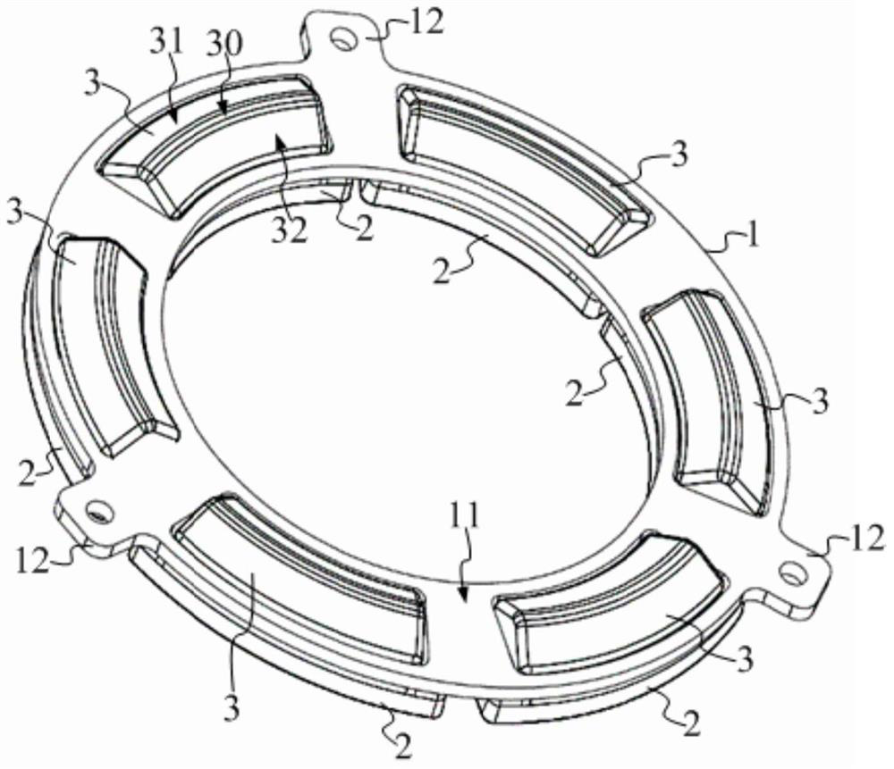
[0033] In the clutch, the clutch pressure plate is arranged between the diaphragm spring and the clutch driven plate, exerts pressure on the diaphragm spring, and the diaphragm spring presses the clutch pressure plate to combine with the clutch driven plate. Release the pressure applied to the diaphragm spring, the diaphragm spring returns, and the clutch pressure plate is separated from the clutch driven plate.

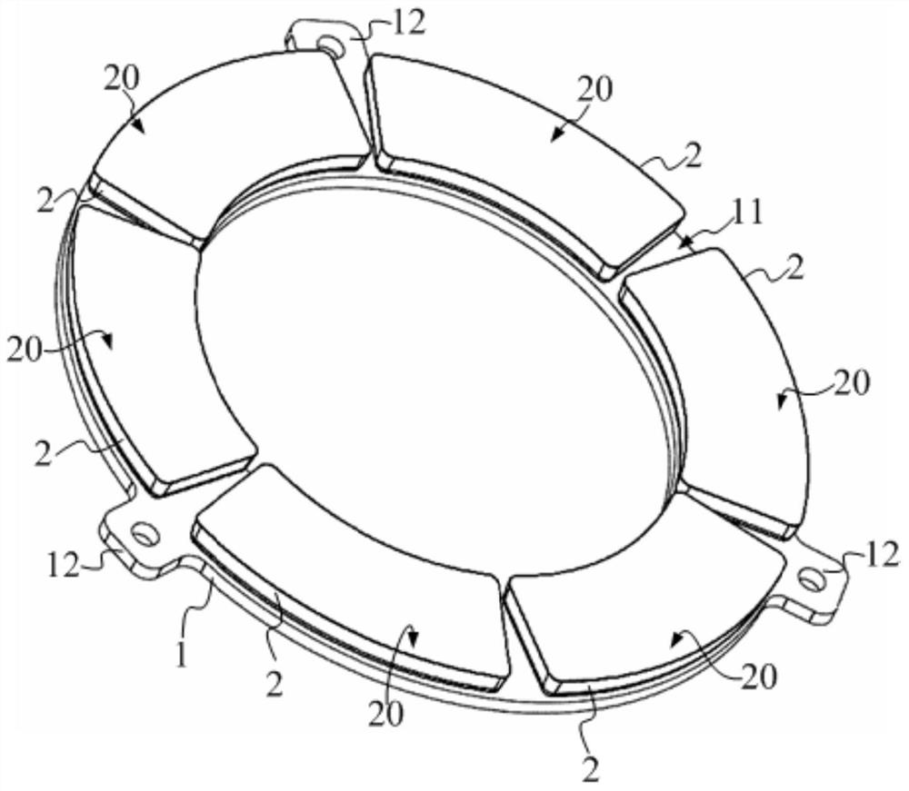
[0034] refer to figure 1 and figure 2 , the clutch pressure plate may include: a support disc 1, the material of which is steel; a friction member 2 arranged on the support disc 1 has a friction surface for frictional combination with the clutch driven disc (not shown in the figure) 20. The friction part 2 is made of cast iron.

[0035] In the clutch pressure plate of the technical solution, the support plate 1 and the friction member 2 are made of different materials, and the two form a split structure. Wherein, the friction surface 20 faces the clutch driven di...

no. 2 example

[0055] Compared with the first embodiment, the second embodiment differs in that:

[0056] refer to Figure 5 , the supporting member 4 and the friction member 5 are connected through the connecting portion 6;

[0057] combined reference Image 6 and Figure 7 , the support member 4 and the friction member 5 are respectively located on both axial sides of the support disc 7 and press the support disc 7 . The support member 4 and the friction member 5 clamp the support disc 7 to realize fixed installation. During assembly, the support member 4 and the friction member 5 can be clamped at the radially inner end of the support disc 7 first, and then the support member 4 and the friction member 5 are pressed into place along the radial direction of the support disc 7 from inside to outside.

[0058] In order to make the installation firm, the connecting part 6 can be provided to connect the support disc 7 in a clamping manner, which can enhance the firmness of the installation ...


PUM


Abstract

A clutch and a clutch pressure plate, wherein the clutch pressure plate includes: a support plate, the material of which is steel; a friction member arranged on the support plate has a friction surface for frictionally combining with a clutch driven plate , the material of the friction member is cast iron. The support plate and the friction parts are composed of separate parts. The steel makes the support plate have high strength, and the cast iron makes the friction parts have high specific heat capacity. The clutch pressure plate of this technical solution integrates the advantages of high specific heat capacity friction parts and high-strength support plate, and has good performance. Torque transmission efficiency and a wider range of applications.

Description

technical field [0001] The invention relates to the technical field of clutches, in particular to a clutch and a clutch pressure plate. Background technique [0002] The clutch is the transmission mechanism between the engine and the transmission, including the clutch pressure plate and the clutch driven plate. The clutch pressure plate always rotates with the engine flywheel. When the clutch is engaged, the clutch pressure plate is manipulated to be in contact with the clutch driven plate to transmit torque. [0003] Existing a clutch pressure plate is made of cast iron material. The cast iron material has a high specific heat capacity. When the clutch pressure plate is in contact with the clutch driven plate, it can absorb heat quickly and dissipate it quickly, ensuring good torque transmission efficiency between the clutch pressure plate and the clutch driven plate. However, the strength of the cast iron material is not high. When the engine is running at high speed, th...

Claims


Application Information

Patent Timeline
Patent Type & Authority Patents(China)
IPC IPC(8): F16D13/70
Inventor 克里斯蒂安·阿萨尔
Owner SCHAEFFLER TECH AG & CO KG
Why Eureka
Try Eureka