Time-resolved fluorescence measuring system based on multichannel TCSPC and multiple detectors
A technology for time-resolved fluorescence and measurement systems, applied in fluorescence/phosphorescence, material excitation analysis, etc., can solve the problems of low counter utilization and weak fluorescence, achieve fast fluorescence lifetime imaging, and improve counting efficiency
- Summary
- Abstract
- Description
- Claims
- Application Information
AI Technical Summary
Problems solved by technology
Method used
Image
Examples
Embodiment 1
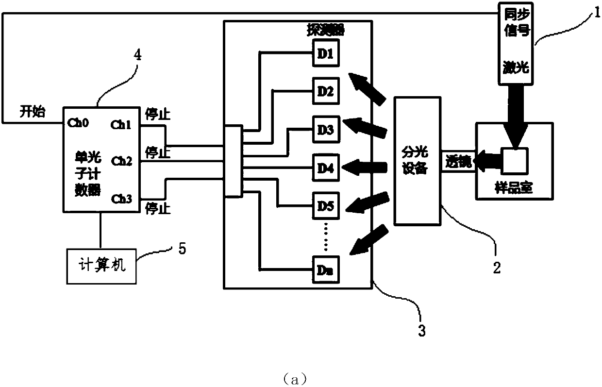
[0020] Such as figure 2 As shown, a time-resolved fluorescence spectroscopy measurement system based on a few-channel time-correlated single-photon counter and multiple detectors according to an embodiment of the present invention includes: a laser light source 1, a spectroscopic component 2, a plurality of single-photon detectors 3, A time-correlated single photon counter 4 and a computer 5 .
[0021] The laser light source 1 is used to emit high-frequency pulsed laser to excite the sample to emit fluorescence. The sample is placed in the sample chamber. The fluorescence emitted by the sample reaches the spectroscopic assembly 2 through the lens, where the main function of the lens is to focus the fluorescence onto the detector. The light splitting component 2 is used to separate the fluorescent light of different wavelengths in space. The light splitting component can be a dispersion element such as a grating or a prism. A plurality of single-photon detectors 3 include ...
Embodiment 2
[0041] The solution of Embodiment 2 of the present invention will be introduced below. Here, only the parts different from Embodiment 1 will be described in detail, and the same parts will not be described again. Generally, when the number of photon detectors is small, the number of channels of the single photon counter may only have two channels, the first channel and the second channel, except the zeroth channel ch0. In this case, set the connecting cables between each photon detector to equal length L, such as Figure 5 shown.
[0042] In this embodiment, different from Embodiment 1, the arrival time measured by the first channel is determined according to the time difference between the photoelectric pulse signal of a certain photon detector arriving at the first channel and the second channel of the single photon counter Corresponding photon detector number.
[0043] In this scheme, since the connection lines (cables) between each detector are preset to be equal in leng...
Embodiment 3
[0047] The solution of Embodiment 3 of the present invention will be introduced below. Here, only the parts different from Embodiment 1 will be described in detail, and the same parts will not be described again. Such as Figure 6 As shown, in the case that the number of photon detectors is large, the number of channels of the single photon counter can have the first channel, the second channel, the third channel and the fourth channel except the zeroth channel, and the multiple The spatial positions of the photon detectors are set as a two-dimensional array, and each detector is connected to the cable a and the cable b in a grid-like manner. The two ends of cable a are respectively connected to ch1 and ch2 of the single photon counter, and the two ends of cable b are respectively connected to ch3 and ch4 of the single photon counter. Any detector in the array receives a photon, and its signal will be transmitted to four channels ch1, ch2, ch3 and ch4, corresponding to four t...
PUM
 Abstract
Description
Claims
Application Information
 - R&D
- Intellectual Property
- Life Sciences
- Materials
- Tech Scout
- Unparalleled Data Quality
- Higher Quality Content
- 60% Fewer Hallucinations
Browse by: Latest US Patents, China's latest patents, Technical Efficacy Thesaurus, Application Domain, Technology Topic, Popular Technical Reports.
© 2025 PatSnap. All rights reserved.Legal|Privacy policy|Modern Slavery Act Transparency Statement|Sitemap|About US| Contact US: help@patsnap.com


