

Two-level particle product screening device for chemical production
A technology of chemical production and secondary sieving, which is applied in the direction of separating solids from solids with airflow, filtering and sieving, and solid separation. To avoid problems such as slow separation speed, achieve the effect of accelerating shaking and dispersion, ingenious structure, and increasing screening rate
- Summary
- Abstract
- Description
- Claims
- Application Information
AI Technical Summary
Problems solved by technology
Method used
Image

Examples
Embodiment Construction
[0018] Below in conjunction with specific embodiment, the technical scheme of this patent is described in further detail:
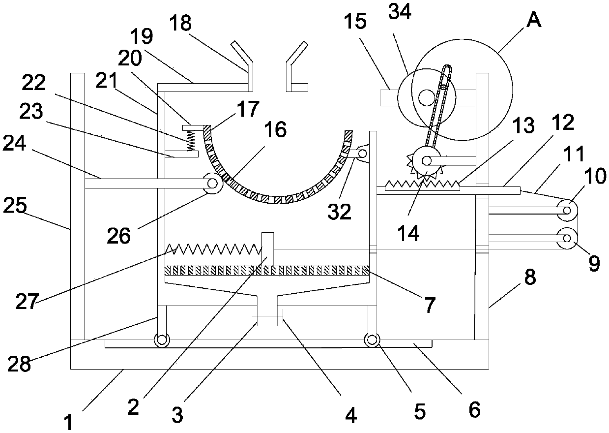
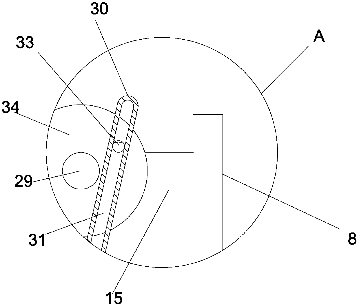
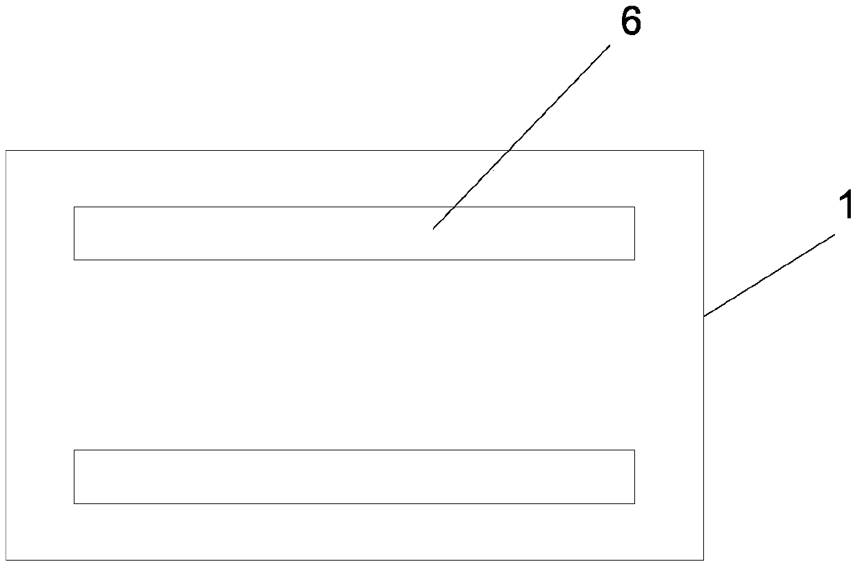
[0019] see Figure 1-3 , a secondary screening device for granular products used in chemical production, comprising a bottom plate 1, a left vertical plate 25 and a right vertical plate 8 are vertically and fixedly installed on the bottom plate 1, and two parallel limiters are arranged horizontally and horizontally on the bottom plate 1 Position groove 6, bottom plate 1 is provided with screening groove 21, the bottom of screening groove 21 is vertically fixed with support leg 28, and the lower end of support leg 28 is provided with the wheel 5 that rolls and is embedded in the limit groove 6 inside; The bottom of the screening tank 21 is vertically provided with a discharge pipe 3, a valve 4 is installed on the discharge pipe 3, a sieve plate 7 is installed horizontally in the screening tank 21, and a scraper is provided on the upper surface of the sieve...
PUM
 Abstract
Description
Claims
Application Information