Inner hole clamping device

A technology of clamping device and inner hole, which is applied in the field of quick pick-up device for parts and components, can solve the problems of unreliable clamping and picking of workpieces with small inner holes and inner holes, so as to ensure reliability, ensure high-precision clamping, and improve clamping reliability effect

Pending Publication Date: 2018-02-02
昆山巨林科教实业有限公司
View PDF0 Cites 7 Cited by
  • Summary
  • Abstract
  • Description
  • Claims
  • Application Information

AI Technical Summary

Problems solved by technology

[0003] In view of the above problems, the present invention provides an inner hole clamping device, which can solve the problem that the traditional spring sleeve cannot reliably clamp and pick up small inner holes, large self-weight, and long inner hole workpieces, so as to meet the needs of industrial robots. Requirements for automated production

Method used


Image

  • Inner hole clamping device
  • Inner hole clamping device
  • Inner hole clamping device

Examples


Embodiment Construction

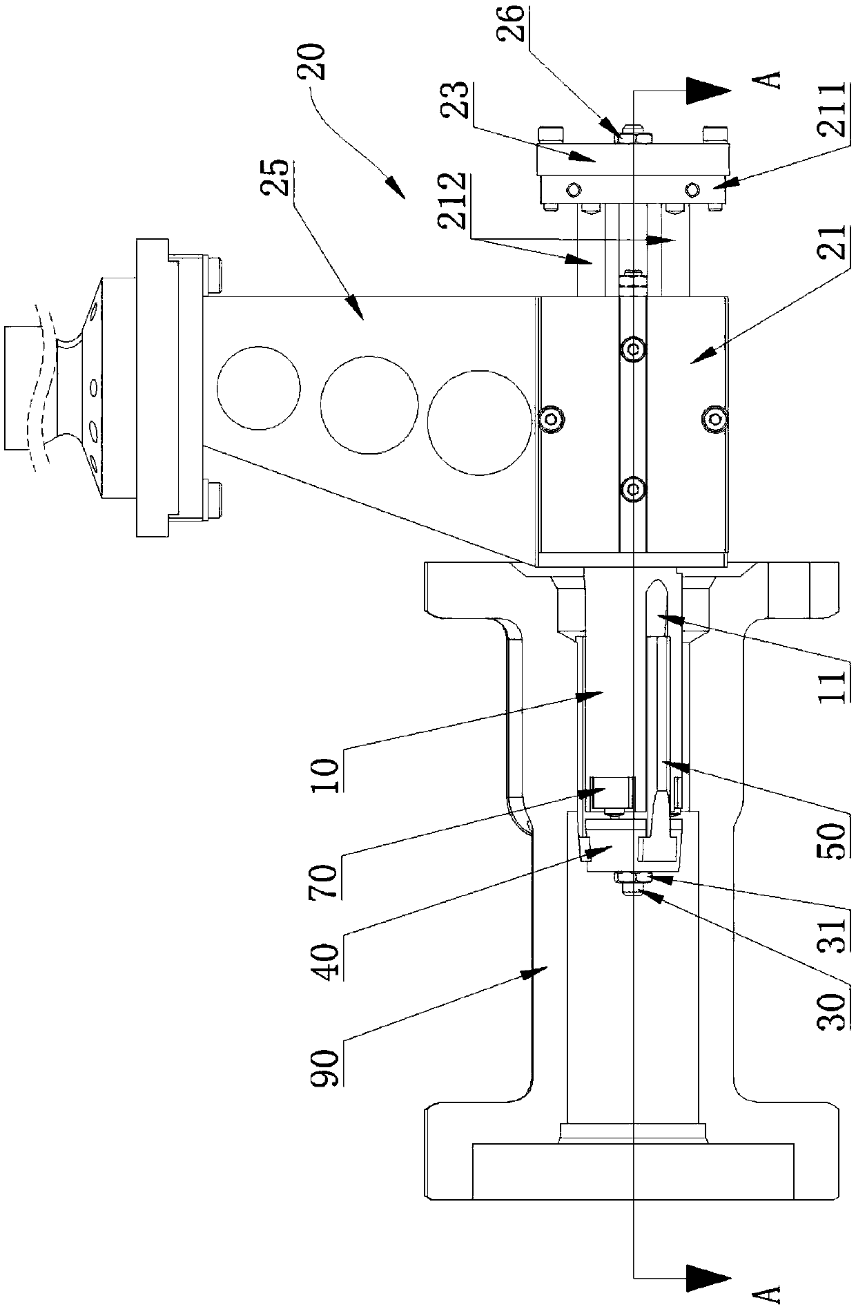
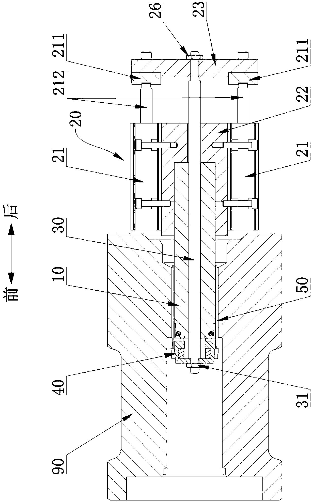
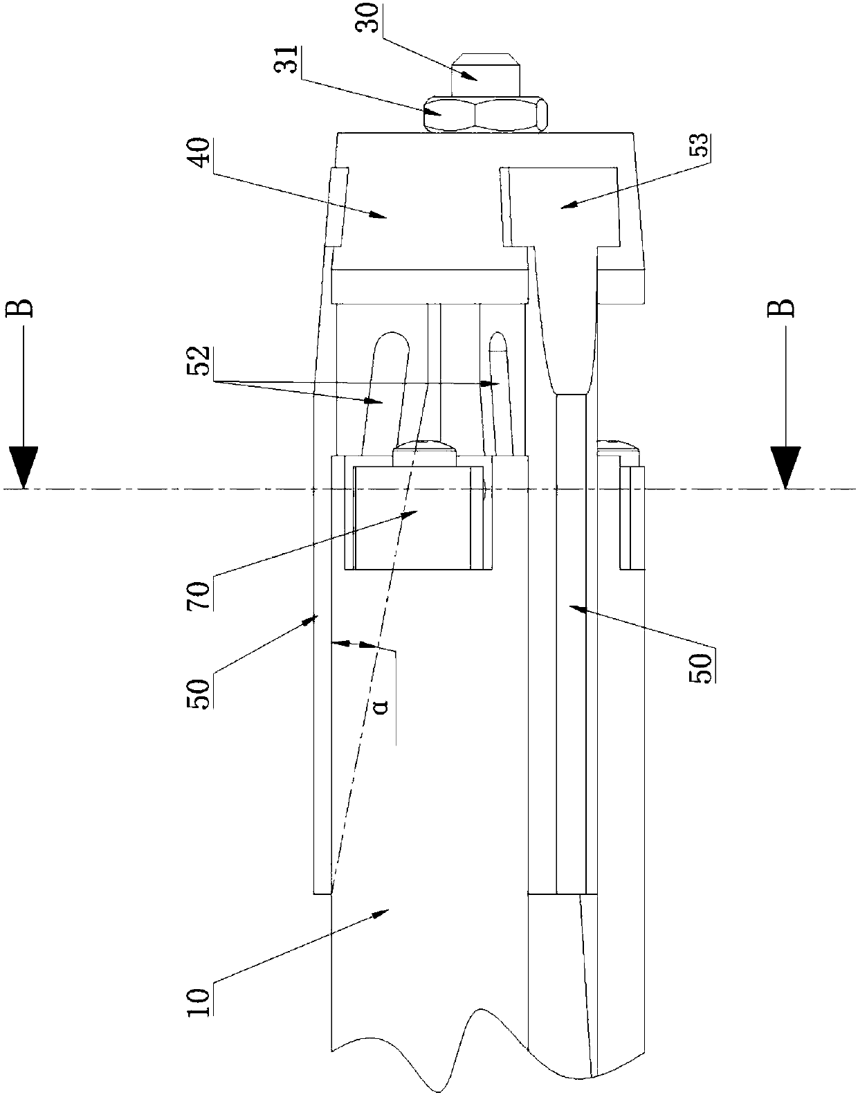
[0035] See Figure 1 to Figure 5 , the inner hole clamping device, which includes a mandrel 10 and a driving mechanism 20, the mandrel 10 is provided with an axial center through hole, and an axially movable pull rod 30 is provided through the axial center through hole, and the front end of the pull rod 30 is connected with The pulling block 40 and the rear end are connected to the driving mechanism 20. The outer peripheral surface of the front end of the mandrel 10 is evenly distributed along the circumferential direction with three slide grooves 11 extending horizontally in the axial direction and parallel to each other. The wedge-shaped groove surface 111 gradually increases forward, the angle α between the wedge-shaped groove surface 11 of the chute and the axial horizontal plane is 5°-20°, and a sliding claw 50 is respectively accommodated in the three chute grooves 11, and the sliding claw 50 is provided with The wedge-shaped inclined surface 51 that cooperates with the ...


PUM


Abstract

The invention provides an inner hole clamping device, which can solve the problem that the traditional spring sleeve cannot reliably clamp and pick up workpieces with small inner holes, large self-weight, and long inner holes, so as to meet the requirements of automatic production of industrial machinery . It includes a mandrel and a driving mechanism. The mandrel is provided with an axial center through hole, and an axially movable pull rod is installed through the axial center through hole. The outer peripheral surface of the front end is evenly distributed along the circumferential direction with three slide grooves that extend horizontally in the axial direction and are parallel to each other. The sliding claw and the sliding claw are provided with a wedge-shaped inclined surface cooperating with the wedge-shaped groove to slide, and the front end of the sliding claw is fixedly connected with the pulling block.

Description

technical field [0001] The invention relates to the field of fast picking devices for parts of industrial robots, in particular to an inner hole clamping device. Background technique [0002] Most of the existing clamping devices for inner hole parts use spring sleeves, which produce radial elastic deformation by applying a large tension to the spring sleeves so as to be tensioned with the inner holes of the parts to achieve clamping movement. Purpose; it has the advantages of low cost and large tension force; however, the tension and release stroke range of the spring sleeve is small, and it requires a large driving force, especially for small inner holes, large self-weight and length For parts with long inner holes, traditional spring sleeves cannot reliably perform clamping operations. Often, the workpiece is easy to fall off when clamping, and the spring sleeve is easy to get stuck with the inner hole of the workpiece when it is released. Therefore, it cannot meet the re...

Claims


Application Information

Patent Timeline
Patent Type & Authority Applications(China)
IPC IPC(8): B25J15/02B25J15/10B65G47/90
CPCB25J15/02B25J15/10B65G47/90
Inventor 姜方毅张国忠费亚军
Owner 昆山巨林科教实业有限公司
Why Eureka
Try Eureka